Documentation Library
Qubic System — product manuals and technical documentation.
76 manuals
·
6 categories
Software
Software applications and simulation guides
Hardware
Motion platform hardware manuals
Tutorials
Step-by-step guides and tutorials
Product Cards
Product specification sheets and datasheets
Miscellaneous
Wallpapers and additional resources
3D Prints
3D printable models for motion platforms


QS-H13
User manual for QS-H13.
1 Safety precautions
Read all safety instructions before installing and using this product. Save this document for future reference. If ownership of this product is transferred, be sure to include this manual. Following coloured frames are used in this manual to draw attention to important information or warnings:Info
The instructions included in this frame indicate information that is considered important, but not injury- or damage-related.
Warning
The instructions included in this frame indicate a dangerous situation that, if not avoided, could result in a user injury or device damage.
1.1 General safety
Warning

Keep hands and feet away from the moving parts when device is in motion.
DO NOT reach under the top frame or attempt to connect/disconnect any cables while the device is powered ON. Doing so poses a serious risk of crushing injuries or severe limb damage due to unexpected movement of the frame or top frame installation.
Warning

Always ensure that cockpit attachment points can withstand forces generated by the QS-H13 (approved construction or tested for expected load). Check the cockpit for loose mounting points.
Warning

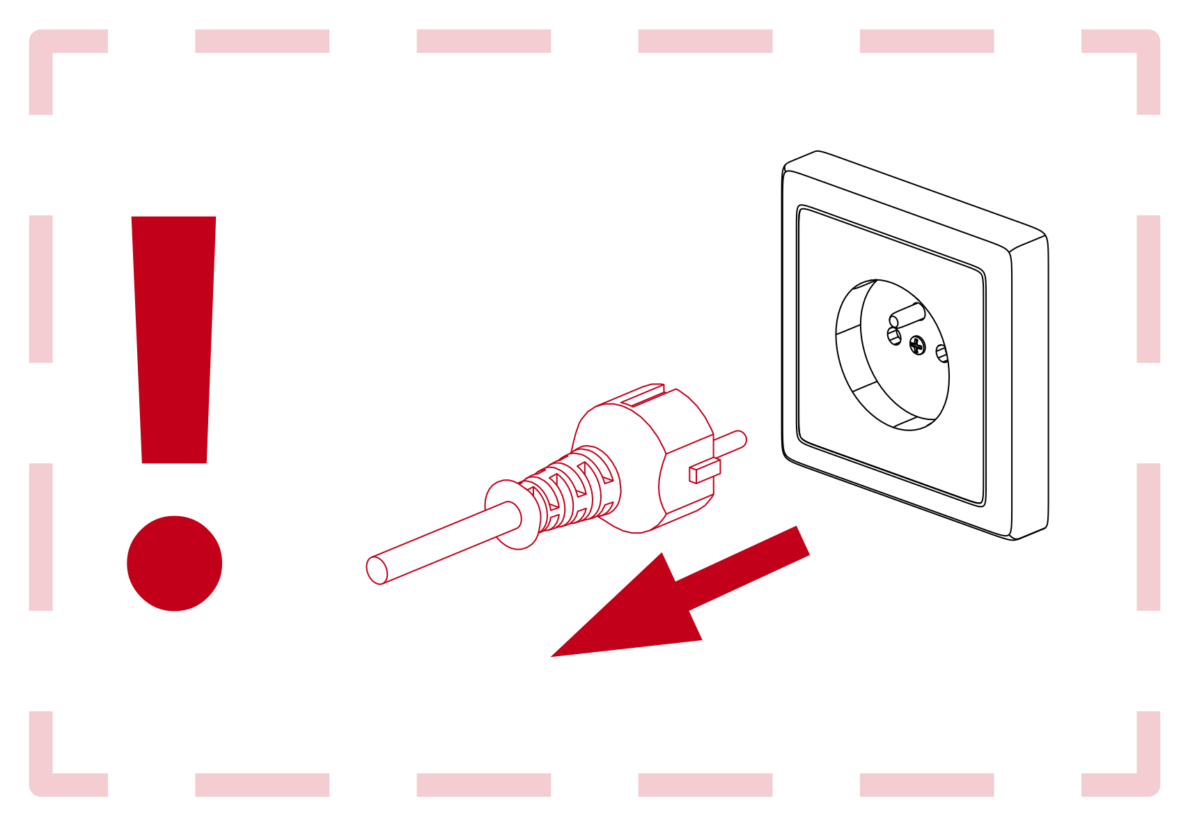
To reduce the risk of burns, fire, electrical shock, injury or mechanical damage always DISCONNECT YOUR POWER SUPPLY from main power socket.
Warning

The device is intended solely for individuals OVER THE AGE OF 16. In case of use by individuals with limited physical, sensory, or mental capabilities, strict supervision is required. Read safety instructions before using the device.
Warning


- The device is NOT allowed to be used by a pregnant woman.
- DO NOT use the device around pets.
- Use the QS-H13 only for its intended purpose, according to instructions.
- Unplug the QS-H13 from the power supply if it is not used for an extended period or when there is a need to perform hardware installation, maintenance, servicing or repairs.
- The QS-H13 was designed for indoor use only - DO NOT store or use the product outdoors.
- Keep the QS-H13 away from the heat sources, high humidity, water, and other liquids. DO NOT store in cold place where water condensation may occur.
- DO NOT disassemble the product. Any tampering with or altering the product will void the warranty, poses a serious risk of electric shock, and may irreparably damage the product.
- Keep the power cord plug and the socket dry, clean and dust-free.
- Protect the power cord from damage caused by being stepped on, rubbed against, or pinched.
- DO NOT use the QS-H13 if the ambient temperature is below 5° Celsius (41° Fahrenheit) or above 40° Celsius (104° Fahrenheit).
- DO NOT use the QS-H13 if it has been damaged, or any component is broken or missing. Please contact technical support.
- DO NOT use attachments or replacement parts not recommended or approved by the manufacturer. If you must replace a power cord, use only certified products with the same rating as the one being replaced.
- Modification of the device's construction and equipment requires a reassessment of compliance.
- Connect the QS-H13 to a properly grounded outlet only.
1.2 Health and safety instruction
The safety of Qubic System users is the top priority. To protect users and bystanders against injuries caused by mechanical parts movement and electrical connectivity, the following instructions must be strictly performed.Warning
As with any mechanical device, the user is responsible for inspecting the condition of the machine prior to use and adhering to safe operating procedures.
- DO NOT use the QS-H13 with the cockpit on a very soft or fragile surfaces like glass or foam.
- Ensure that QS-H13 is mounted properly to a cockpit.
- Be aware that QS-H13 can move the cockpit a little in every direction during operation. Those movements could damage the surface in the long term. Manufacturer, its subsidiaries, and their partners are not responsible for any floor damages.
- DO NOT mount the rig in tight or cluttered spaces - remember that QS-H13 moves and nothing should restrict its motion range.
- Seatbelts and other harnesses should be mounted to the part of the motion rig that moves along with QS-H13 top frame/seat. DO NOT attach them to any static part or ground.
- Cables must not be stretched and should be kept in a way that prevents them from getting under top frame or any part that can crush or tear them.
- If you want to use the QS-H13 in an unusual application, and you are not sure, that the desired setup is feasible, please contact, the distributor/reseller.
- Check if cables are mounted properly - they are not stretched or loosely connected to the socket.
- Check if there are no objects in the motion range of the platform.
- Check that all elements are properly fixed.
- Check if there are no sharp edges nearby.
- Check if everyone around is aware of machine rapid movements.
- Make sure that no one stands in the range of motion (minimum 1.5 m).
How to safely turn on and use the QS-H13 :
WarningQS-H13 will move automatically after turning it on in order to perform a calibration procedure. User may seat in the QS-H13 during the calibration run - be aware of the movement.
- Ensure that no one stands in the working range of the platform.
- If a Motion Lock button is implemented - make sure it is pressed (Motion Lock ON).
- Power the QS-H13 ON.
- If a Motion Lock button is implemented - unpressed it by twisting.
- QS-H13 will perform a calibration run.
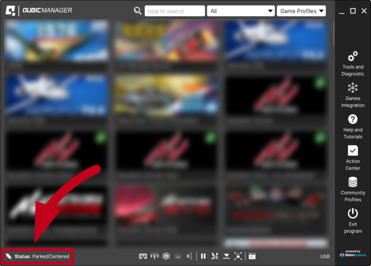
- When the QubicManager device status in the bottom left corner says "Running" or "Parked/centered" - the QS-H13 is ready to operate, once the game is launched.
- For VR Headset users:
- Remove the VR goggles before entering or exiting the rig.
- Ensure that VR Headset is not limiting the operation range of QS-H13 .
- Check if the whole VR setup is not in range of motion of the machine.
- DO NOT place the connection loosely under the motion rig.
Info
It is recommended that the connected PC is capable of running the game at stable 90 frames per second or more when VR Headset is used. Lower values can cause VR sickness.
- DO NOT use QS-H13 if you are pregnant, tired, or under the influence of alcohol or drugs.
- STOP USING the QS-H13 immediately if pain, fatigue or any discomfort appears.
- For every two hours of using the system, we recommend at least 15 MINUTES OF BREAK.
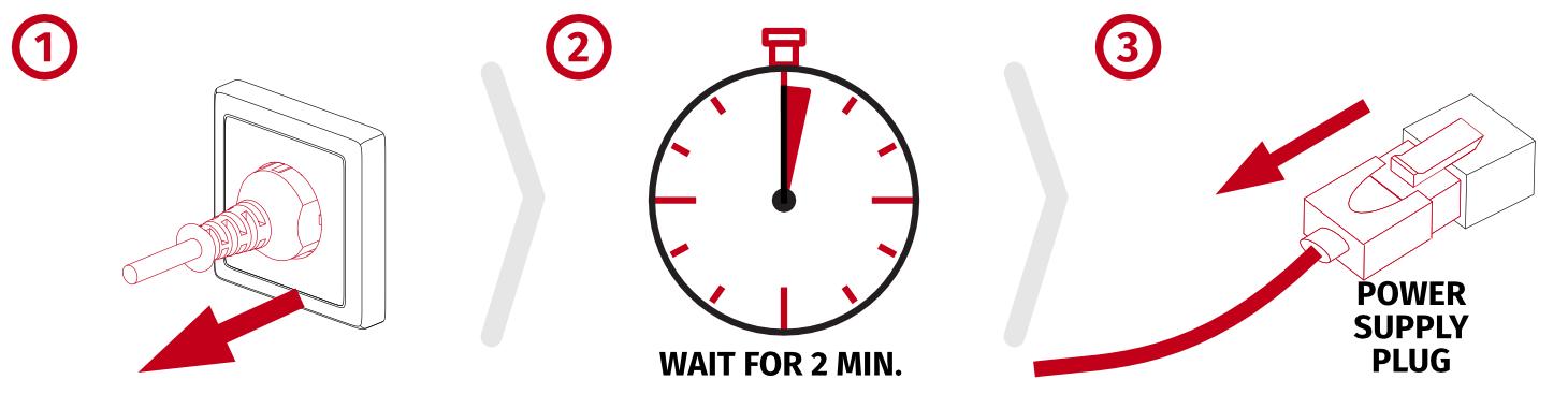
Warning
NEVER disconnect or connect the Power Supply plug to the QS-H13 with Power ON. Wall power plug must ALWAYS be the first to unplug and last to plug in.
More details in section Before connecting power.
More details in section Before connecting power.
2 Product description
The QS-H13 is a compact 2DoF seat mover designed to deliver intense pitch and roll motion, perfectly suited for both sim racing and flight applications. With exceptionally long travel and ultra-fast response times, it provides highly dynamic and realistic movement feedback. Built on the same proven linear actuator technology as the QS-220, it ensures reliability and precision while maintaining a sleek and modern design. Its compact footprint allows for easy mounting with standard aluminum cockpits, making it a versatile choice for enthusiasts. The QS-H13 operates as a fully independent motion system but can also be integrated with the QS-BT1 seat belt tensioner for an even deeper level of immersion.2.1 System components
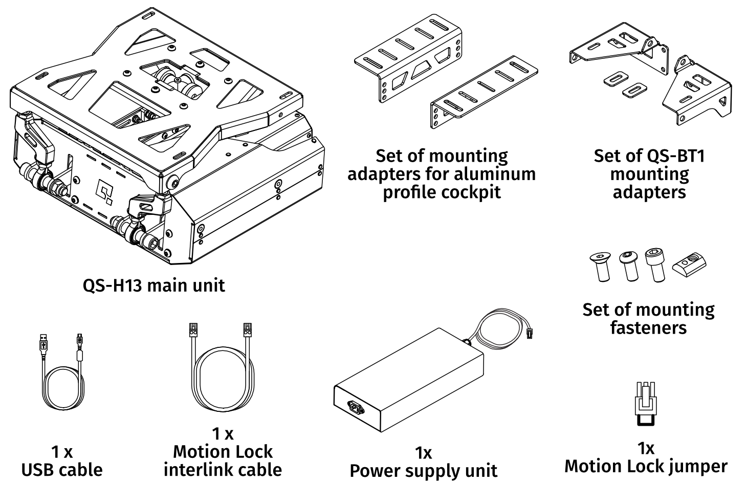
2.1.1 Power Cord
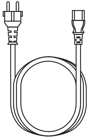
The power cord for QS-H13 is provided as a separate component and is selected based on the electrical standards and socket types applicable in the target market. This ensures compatibility with regional voltage, frequency, and plug configurations.
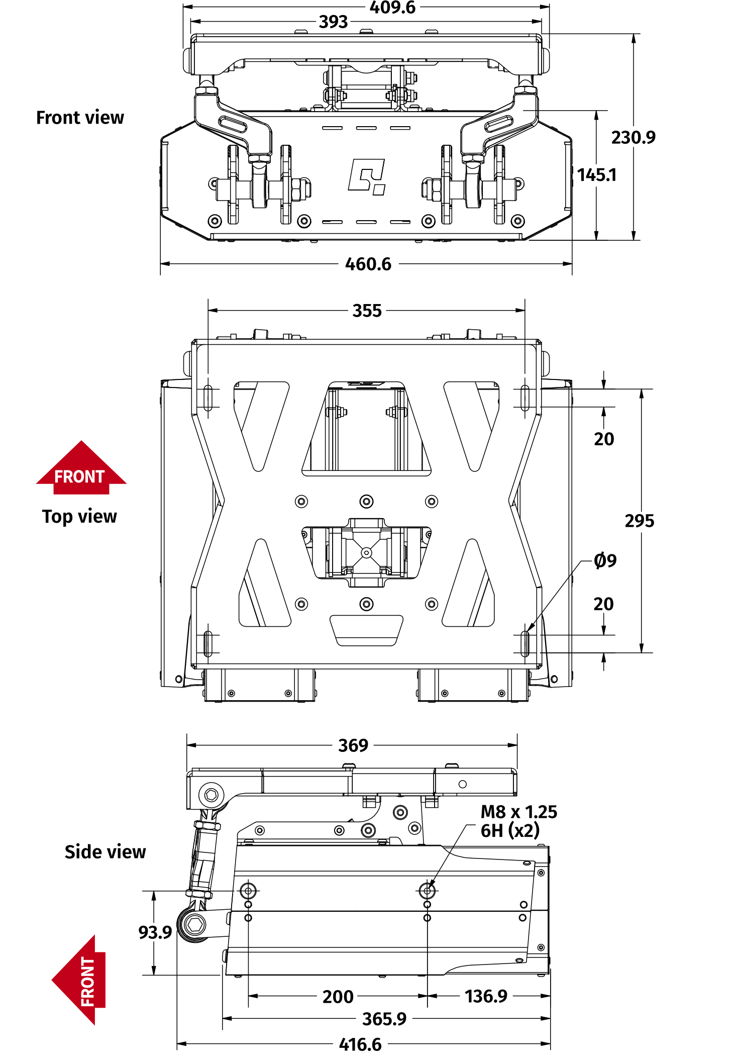
2.2 QS-H13 dimensions
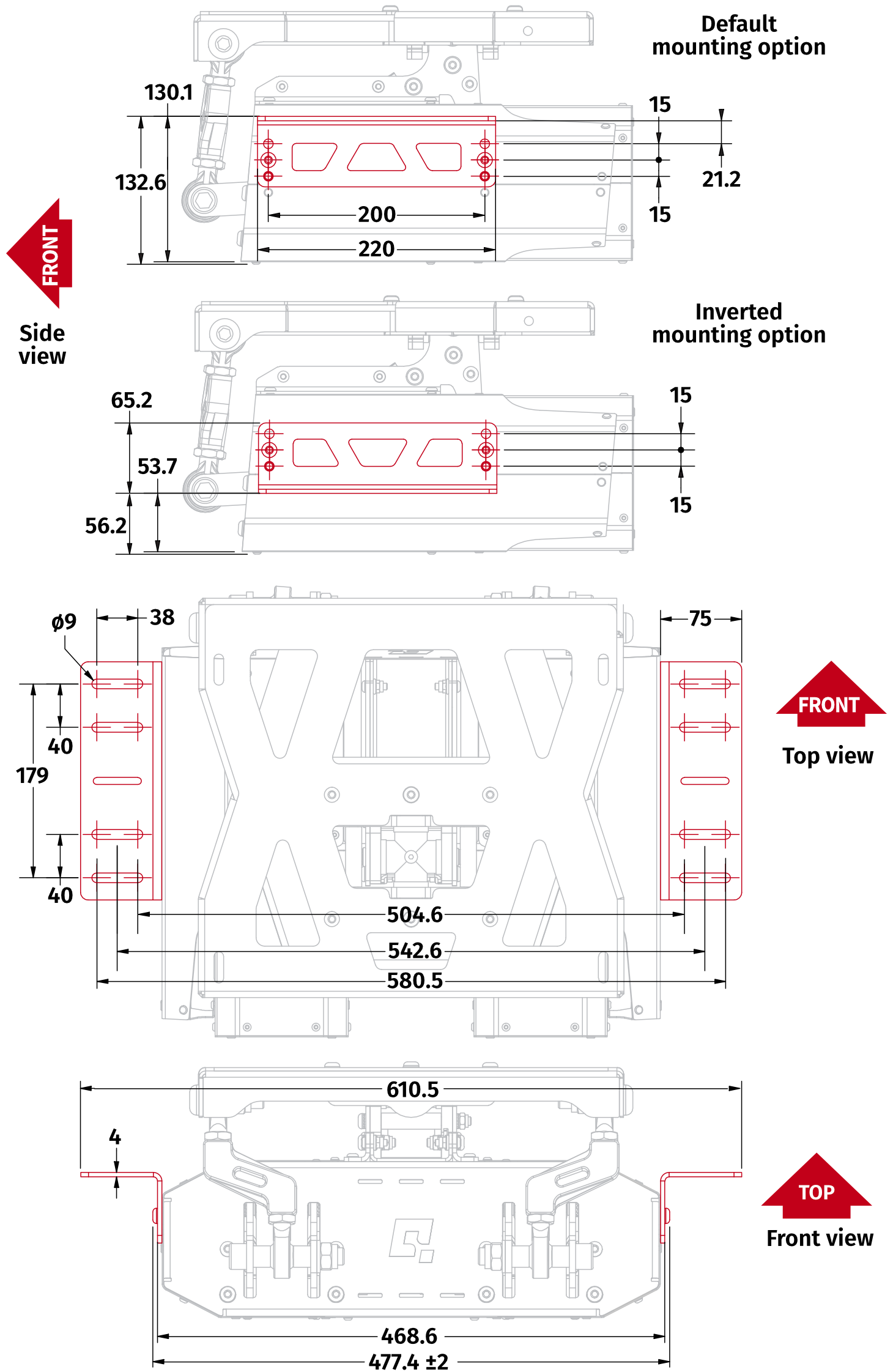
2.3 QS-H13 mounting adapters dimensions
2.4 System specification
| Parameter | |
|---|---|
| Architecture | 2DoF |
| Device weight | 33 kg |
| Maximum user's weight | 130kg |
| Vibration frequency range | 0-100 Hz |
| Performance | Roll | Pitch |
|---|---|---|
| Single Excursion | 10.4°, -10.4° | 9.45°, -9.45° |
| Maximum velocity | 65 deg/s | 50 deg/s |
| Maximum acceleration | 850 deg/s2 | 650 deg/s2 |
2.5 Power specification and consumption
Power Supply Unit contains the power supply for the QS-H13 and it requires between 100 and 240 of input Voltage and operates at 480 Watts of maximum power. If there is no certainty if fuses or entire electrical installation can handle QS-H13 's power consumption, contact a qualified electrician.| Input | ||
|---|---|---|
| Voltage range | Frequency range | Current |
| 100-240VAC | 50-60Hz | 7.0A max
|
| Output | ||||
|---|---|---|---|---|
| Voltage (DC) | Max Current | Max Power | Idle power cons. | Ripple and noise |
| 46V | 10.43A | 480W | 5W (0.005kWh) | ≤ 300mV
|
| Converter specification | Breaker specification | Power consumption | ||||||
|---|---|---|---|---|---|---|---|---|
| Average Power [kVA] | Peak Power [kVA] | Peak Current [A] | Average Power (stress test) [kW] | Average Power (typical game) [kW] | ||||
| 120 V power supply | ||||||||
| 0.080 | 0.100 | 3 | 0.040 | 230 V power supply | ||||
| 0.090 | 0.100 | 2 | 0.030 | 0.006
| ||||
2.6 Power requirements
QS-H13 requires a 120/230± 10% VAC 50-60 Hz single phase with ground and neutral connection.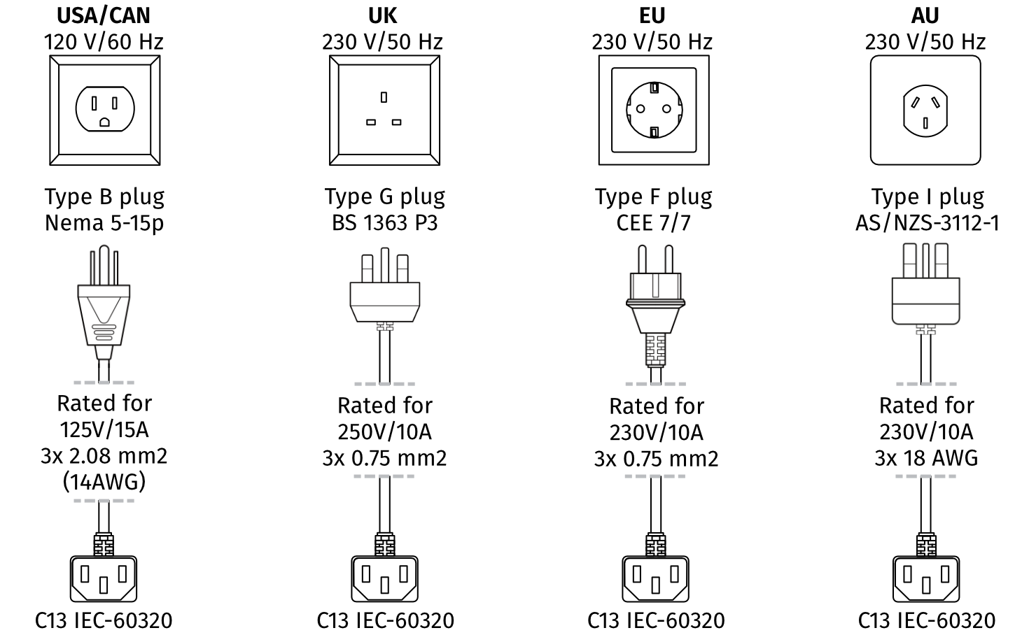
Info
Always UNWIND THE CABLE COMPLETELY when using a cable reel and untangle an extension cord before connecting the device to the power supply.

Warning
- The device is NOT intended to be used in an IT earthing/grounding system.
- The product must be connected to the mains power supply with a protective earth (PE) and a residual current circuit breaker (RCCB).
2.7 Environmental conditions
The QS-H13 should be operated within ambient conditions as specified below:- Indoor use and storage only
- Temperature: 5° - 40° Celsius / 41° - 104° Fahrenheit
- Humidity: 0% - 70% (without water vapor condensation)
- Maximum altitude: up to 2000 m a.s.l. / 6561 ft
2.8 Noise emission
The QS-H13 was checked for noise level based on actual standards. Noise level during normal work conditions is not over 60 dB. Measuring method is compliant with ISO 11202 standard. Four measuring positions as shown on the picture are placed 160 cm from the floor level and 100 cm from the edge of the device.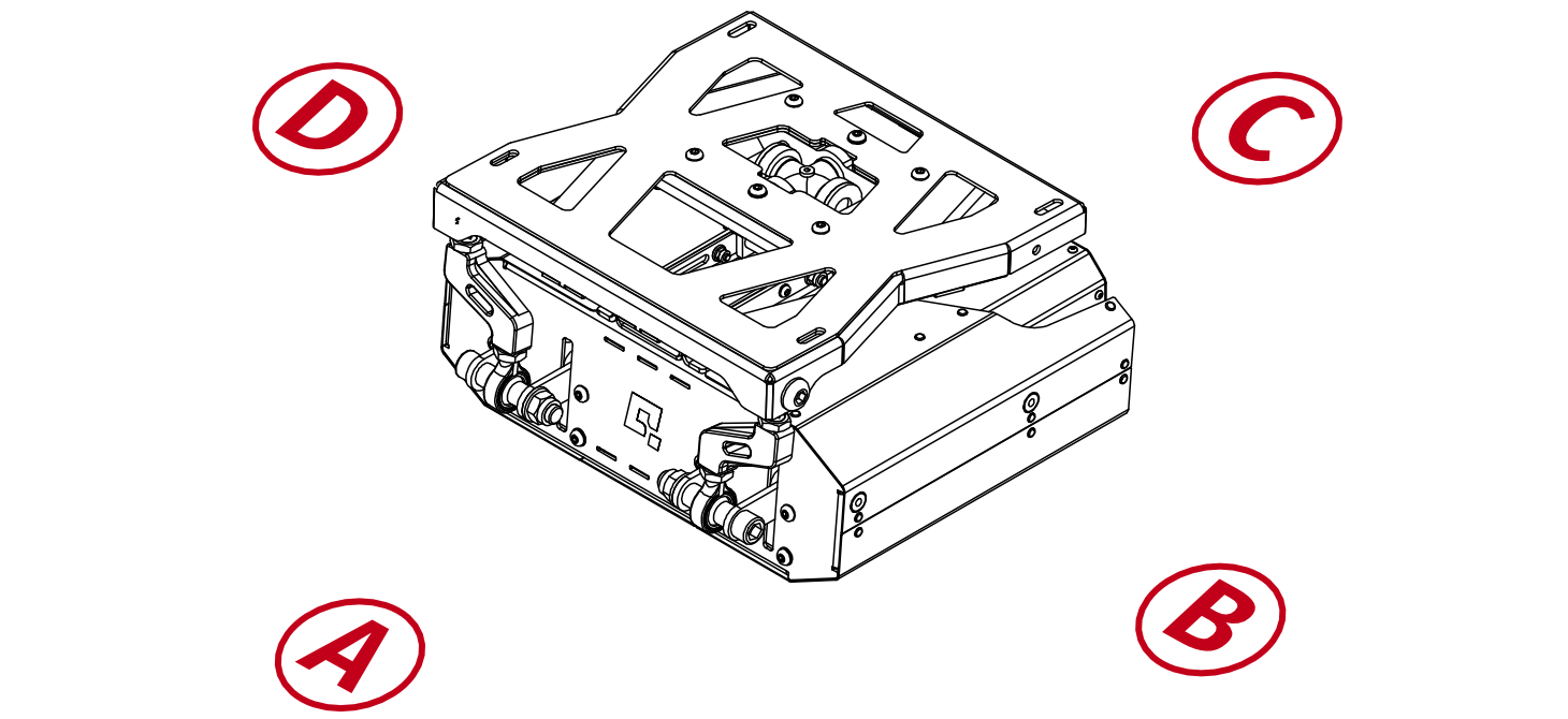
| Measurement point | A | B | C | D |
|---|---|---|---|---|
Measurement conditions:
| 57.3 dB(A) | 55.6 dB(A) | 55.9 dB(A) | 56.6 dB(A) |
Measurement conditions:
| 55.5 dB(A) | 54.3 dB(A) | 53.4 dB(A) | 54.7 dB(A) |
Measurement conditions:
| 56.6 dB(A) | 54.4 dB(A) | 54.1 dB(A) | 55.9 dB(A) |
2.9 Labels and warning sign placement
Warning signs indicate risk areas where the user must not place body parts between the housing and the top frame of the device, as this poses a crushing hazard: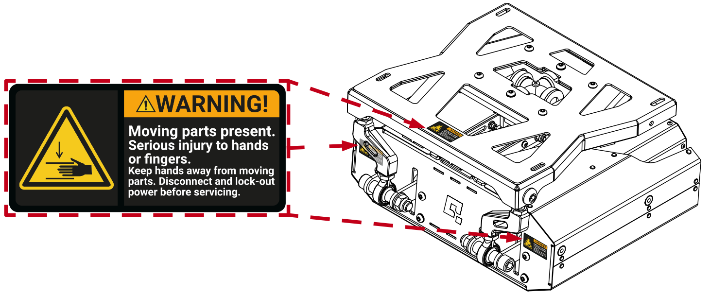
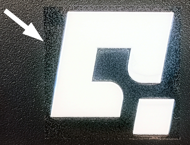
Front logo is protected with a transparent cover sticker - its removal will not damage the logo sticker underneath.
3 Installation
3.1 Pre-installation guidelines
During the installation follow specific guidelines for your safety, device duration and installation efficiency:- Make sure you are equipped with torque wrench and follow the torque specs for each bolt.
Part description Torque ISO 7380-1 bolt M8 17Nm DIN 933 bolt M8 23Nm - Use mild thread locker on every bolt that is not screwed in with a locknut.
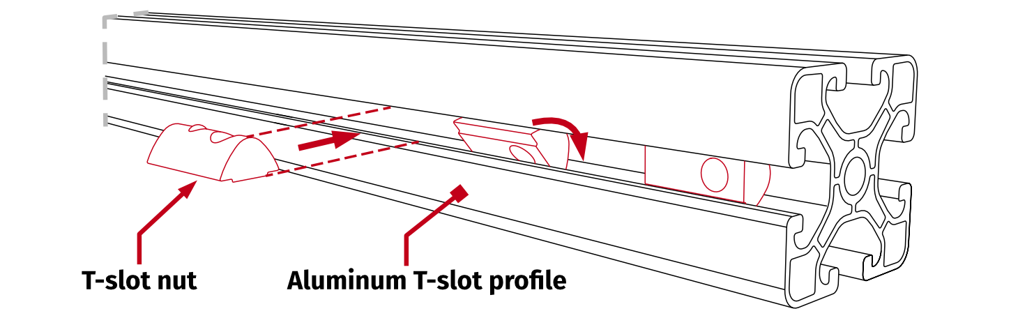
- Keep in mind, that T-slot nuts can be inserted in any given part of the aluminum profile, not only from open ends:
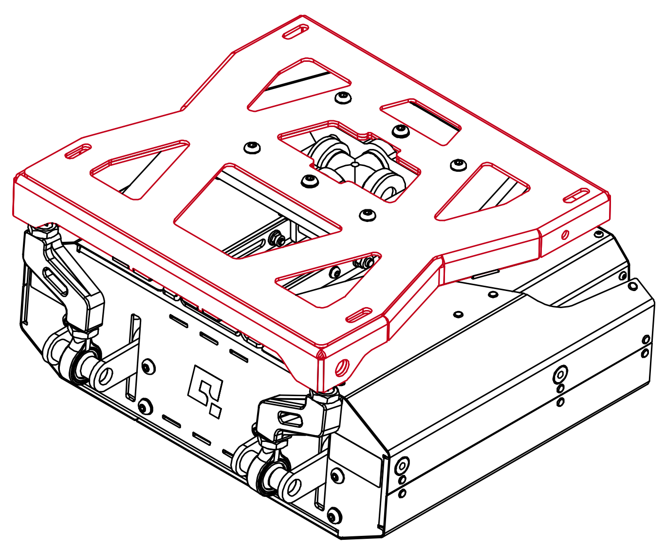
- The device must be lifted by the upper frame:
Info
QS-H13 is fully compatible with Next Level Racing GT Track cockpit - mounted directly to side rails (longer mounting bolts not included).
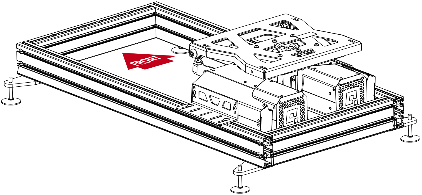
3.2 Mounting to aluminum profile based cockpit
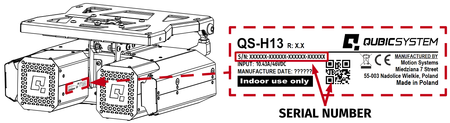
QS-H13 MUST be mounted to a cockpit for stability - preferably to an aluminum profile based cockpit using included universal mounting adapters.Info
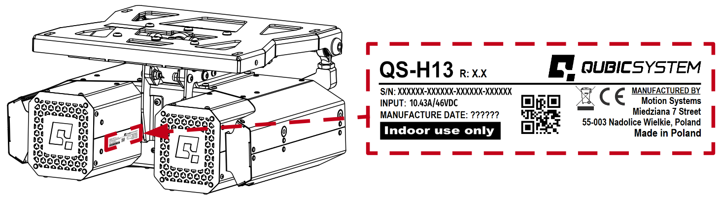
Before installing the QS-H13 to a cockpit - write down Serial Number which can be found on rating plate located on the left motor housing. Refer to section 3.9 for details.
Warning
QS-H13 was designed, manufactured and tested as a seat mover. NO external mounts, frames, pedal trays, rudder controllers, steering wheels, or any other accessories may be attached to the top frame of the device on a horizontal or vertical frame.
Any attempt to fix, fasten, or modify the unit with such equipment may cause damage, create safety hazards, and will void all warranty and service obligations.
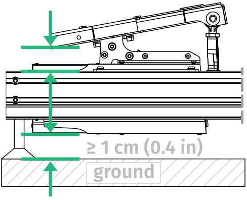
Info
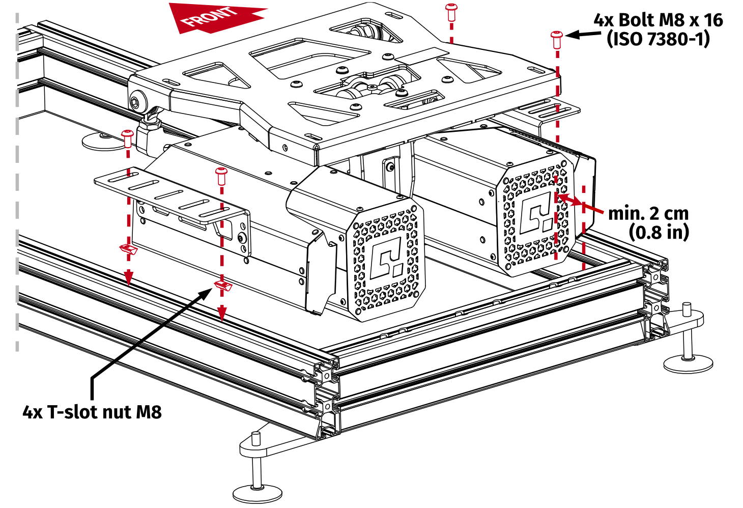
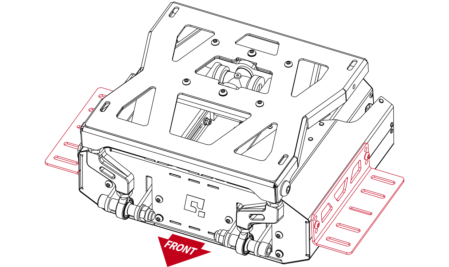
- QS-H13 should be installed as low as possible without creating a collision of device's top frame (and seat adapter brackets) with the top of the aluminum profiles, during maximum roll and pitch motion.
- Ensure that QS-H13 does not stand directly/touch the ground. Adjust cockpit's swivel feet for at least 1 cm (0.4 in) of clearance.
- Screw in the mounting adapters from each side:
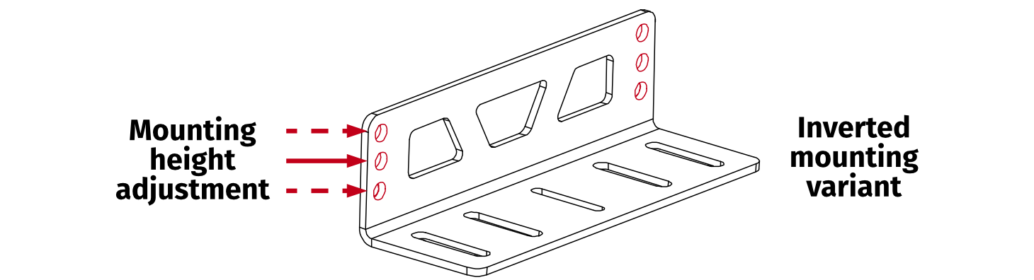
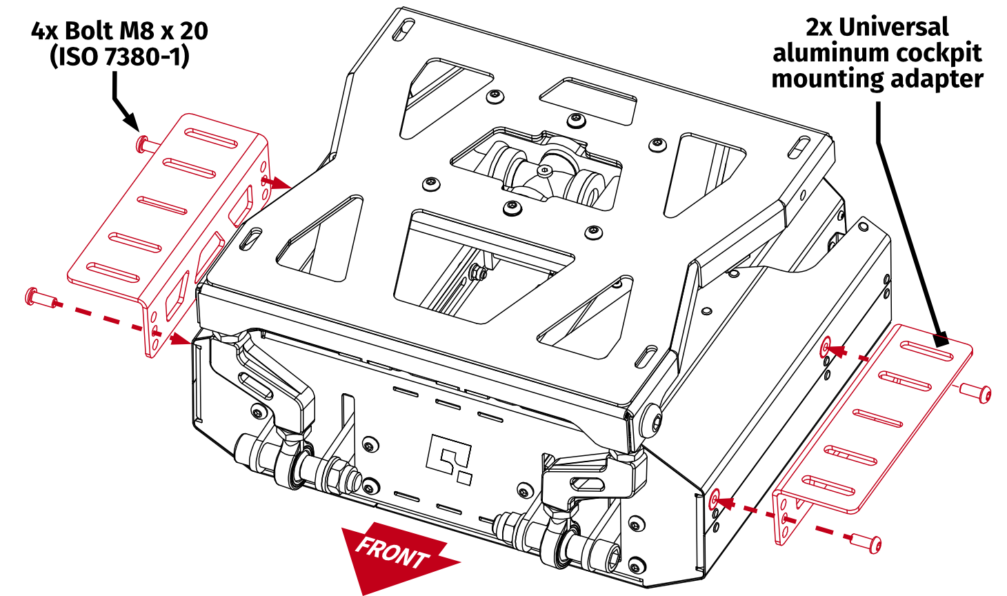 InfoKeep in mind that the mounting adapter have three holes per side in a vertical arrangement to provide mounting height adjustment. For adapter dimensions, go to section 2.3.
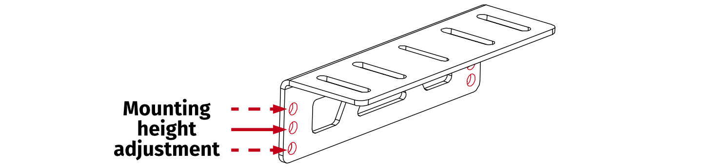
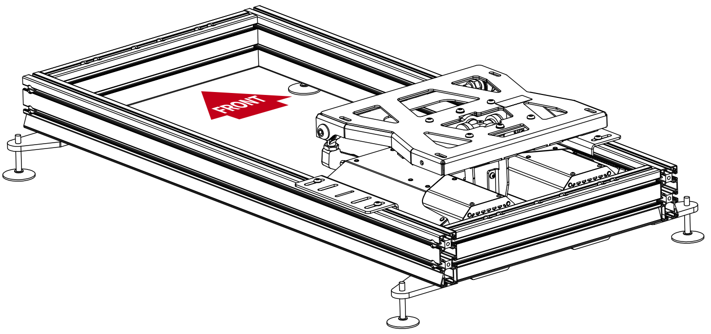
- Screw in the QS-H13 to the top side of the aluminum profiles. Ensure a minimum clearance of 2 cm (0.8 in) between the device and the rear aluminum profile:
Warning
The QS-H13 MUST be mounted to a rigid and structurally stable cockpit capable of withstanding forces generated by the device, including those amplified by the moment of inertia.
The QS-H13 is not designed to function as a structural element and SHALL NOT be used to maintain the cockpit's structural integrity.
Mounting variant for additional height adjustment
Flip the mounting adapter up-side down, for increased height adjustment:
3.3 Mounting a seat to the top frame
Mount the seat to the QS-H13 's top frame using dedicated mounting holes and provided fasteners. Racing seat mounting adapters are not included.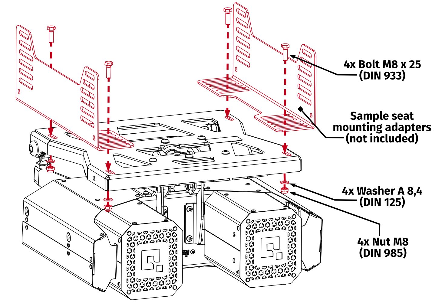
Warning
QS-H13 is a dynamic seat mover with a long travel roll and pitch movement, creating moment of inertia on user's body - it is recommended to use a FIA certified racing seat and harness for safety.
Info
The seat with its adapter should be mounted at the center of the QS-H13 top frame. The position tolerance is referenced to the center of the cardan cross shaft: no lateral deviation is permitted; a maximum of 5 cm (2 in) tolerance is allowed in the forward and backward directions.
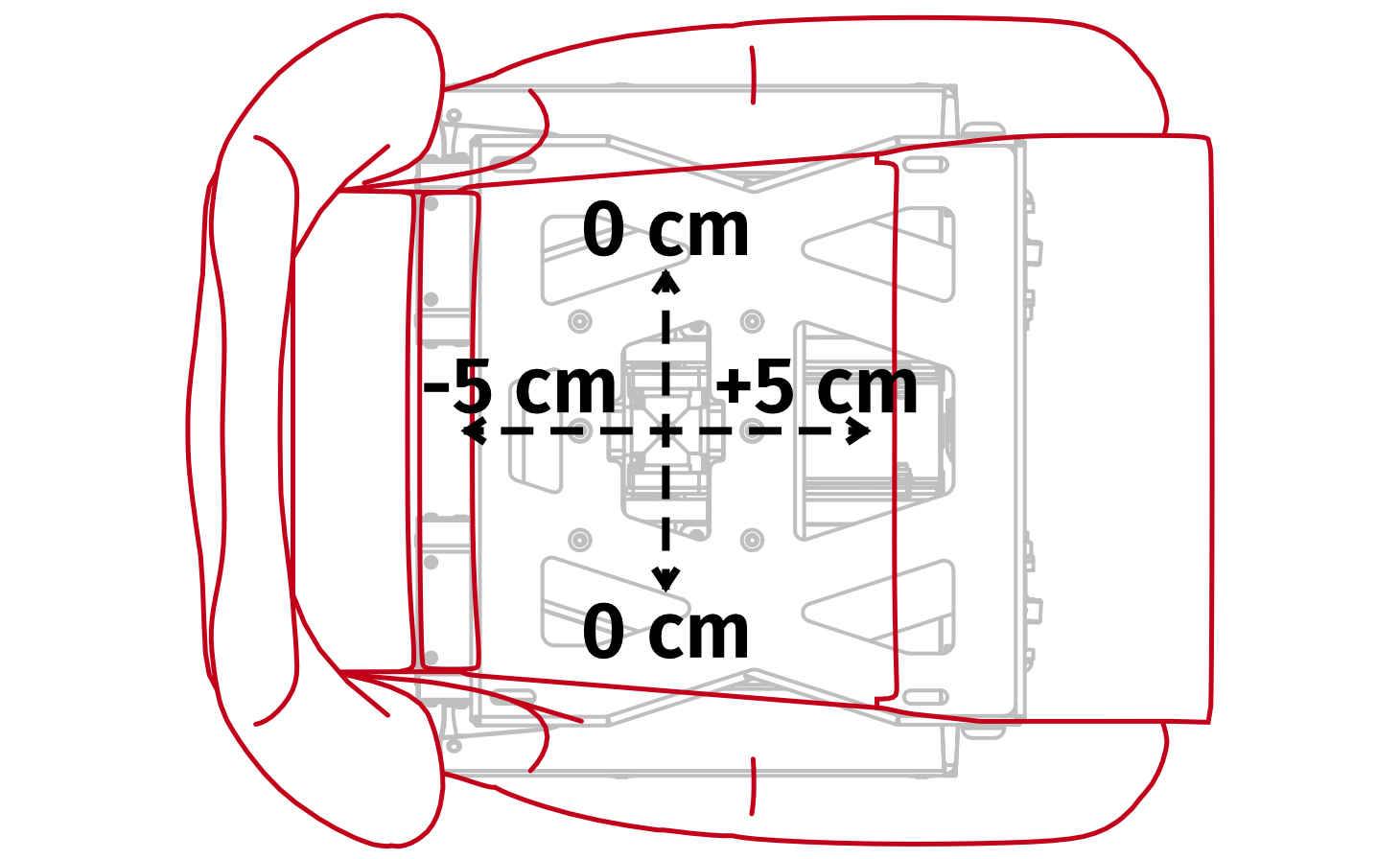 Correct seat mounting will improve the driving experience by reducing unwanted inertia and will extend the life of the device's components.
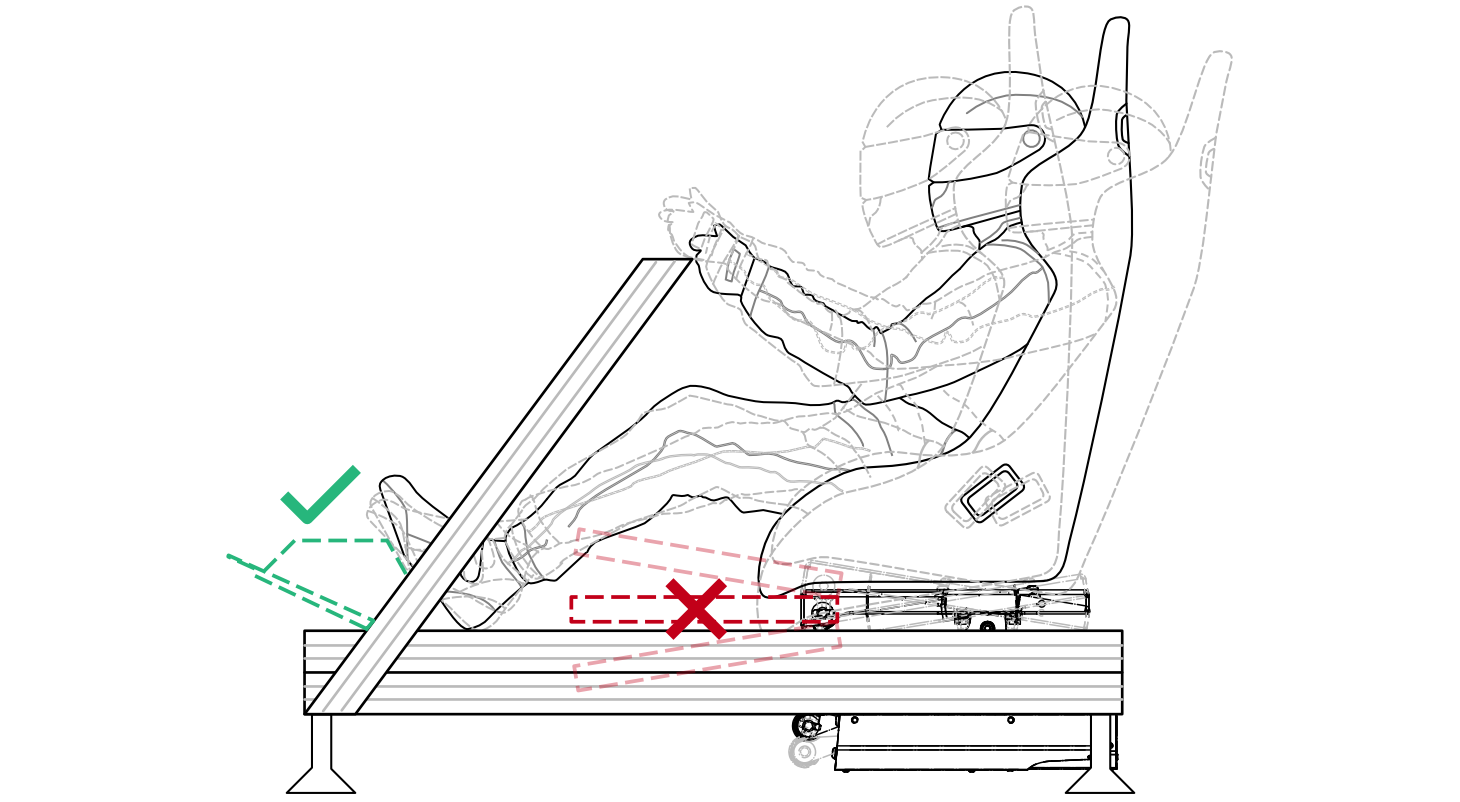
Warning
User's legs must be supported on an element that is NOT a part of QS-H13 's top frame.
3.4 Mounting QS-BT1 to QS-H13
Warning
When installing QS-BT1 to the back of the QS-H13 - ensure there is no possibility of collision of the belt tensioner with your cockpit.
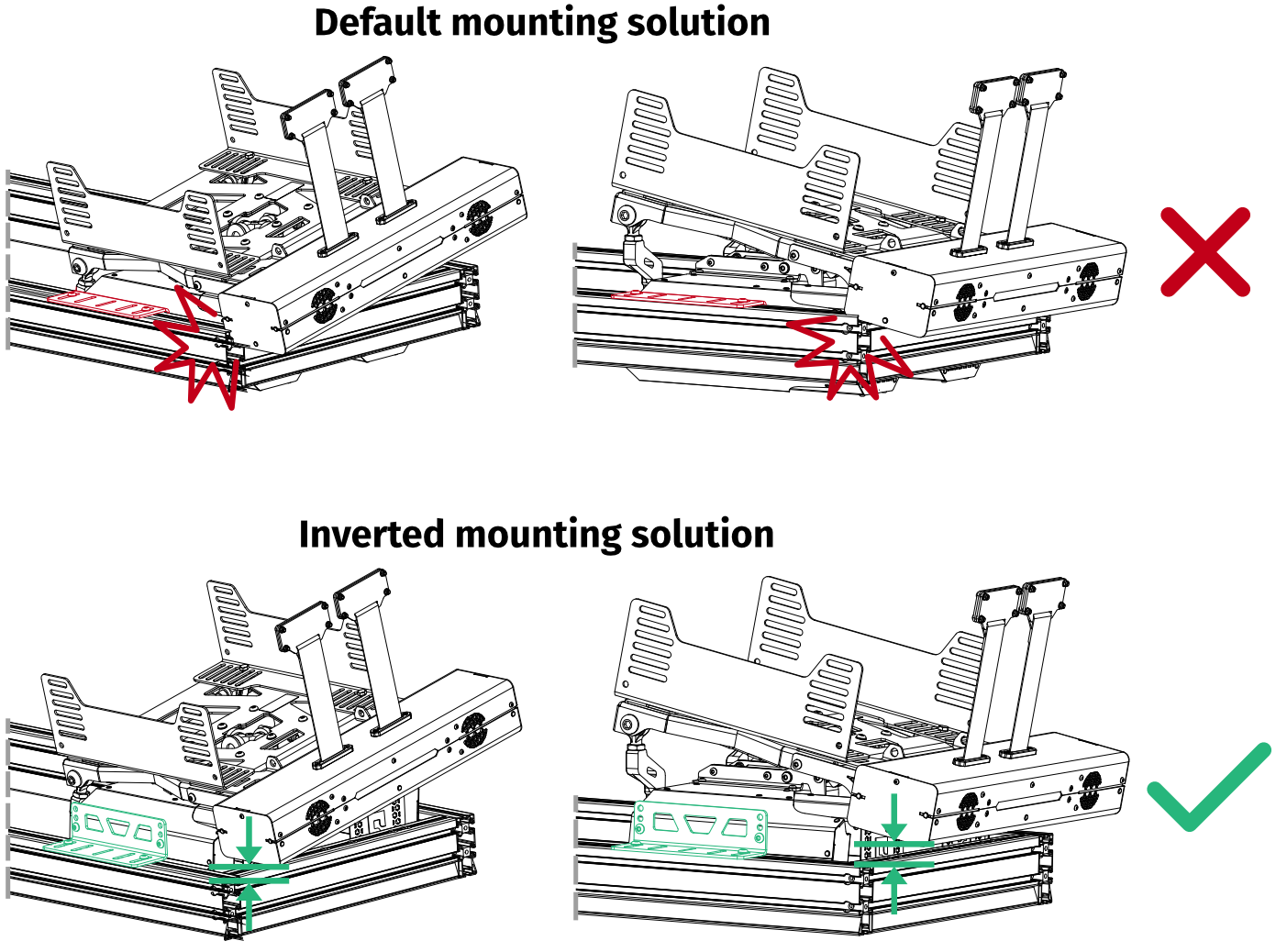
It is recommended to mount the seat mover with an inverted mounting adapter solution to ensure there is no possible trajectory of collision at maximum roll and pitch with side or back cockpit profiles.
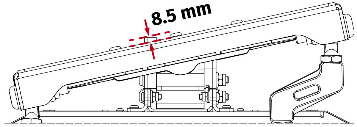
- Set of QS-BT1 mounting adapters must be installed between the seat adapter and QS-H13 's top frame. Use included fasteners:
Illustration of a finished mounting adapter assembly:
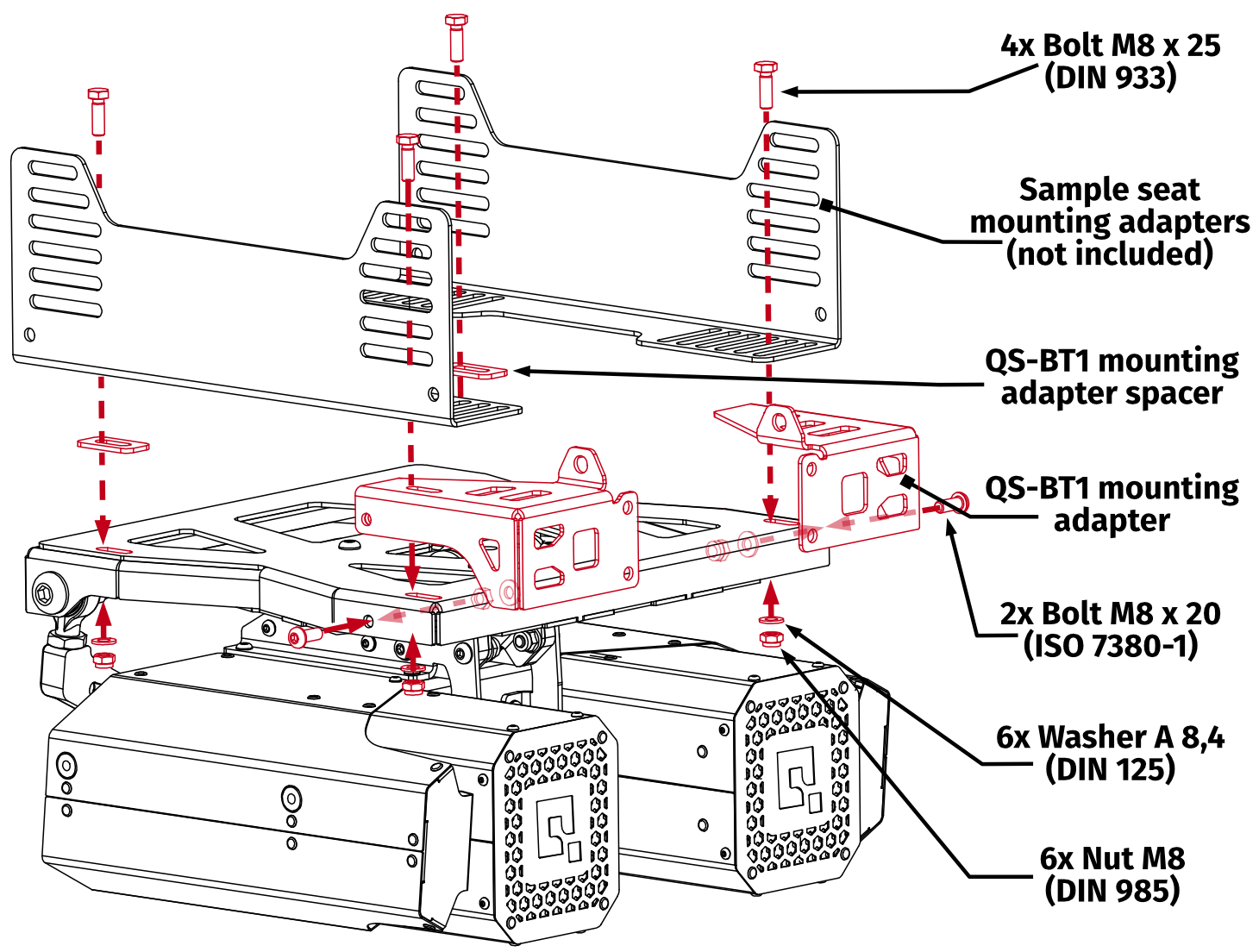
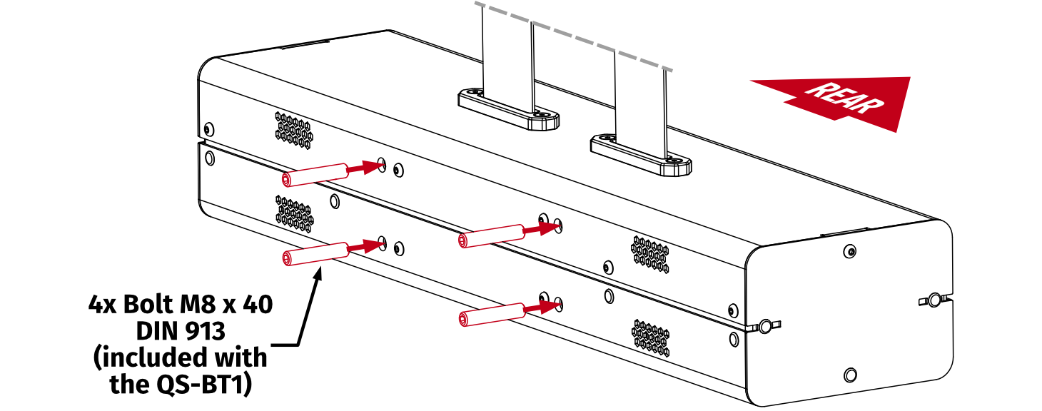
- Screw in included bolts into the QS-BT1. Do not overtorque them - maximum 10 Nm (7.4 ft-lbs) of torque.
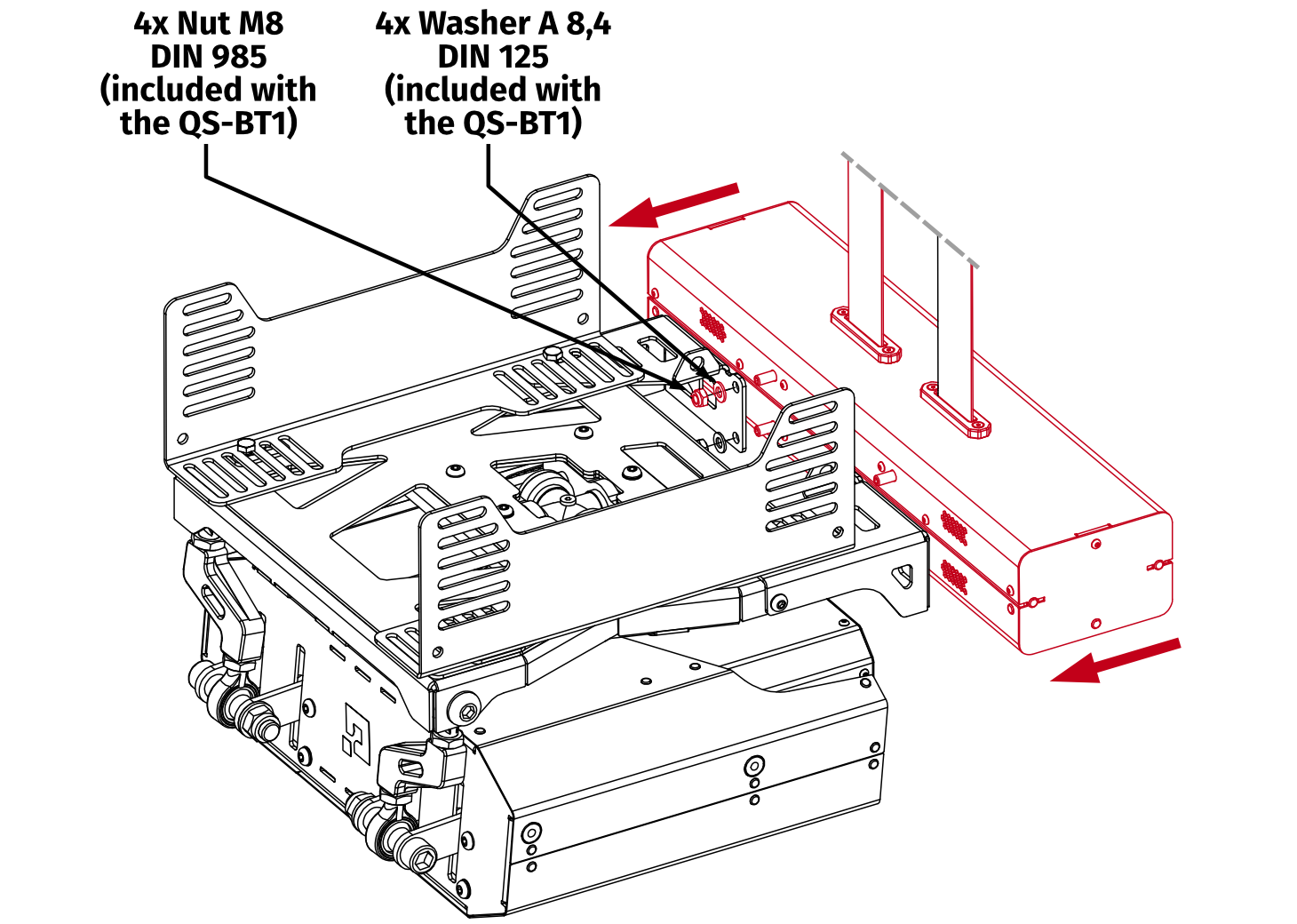
- Mount the QS-BT1 to the backside of QS-BT1 adapters using nuts and washers provided with the belt tensioner.
- In a QS-H13 + QS-BT1 setup it is recommended to mount the seat mover to a cockpit using an inverted mounting adapter solution. It increases the height of the QS-H13 's top frame in order to avoid collisions with a cockpit at a maximum roll and pitch movement.
InfoFor adapter dimensions, go to section 2.3.
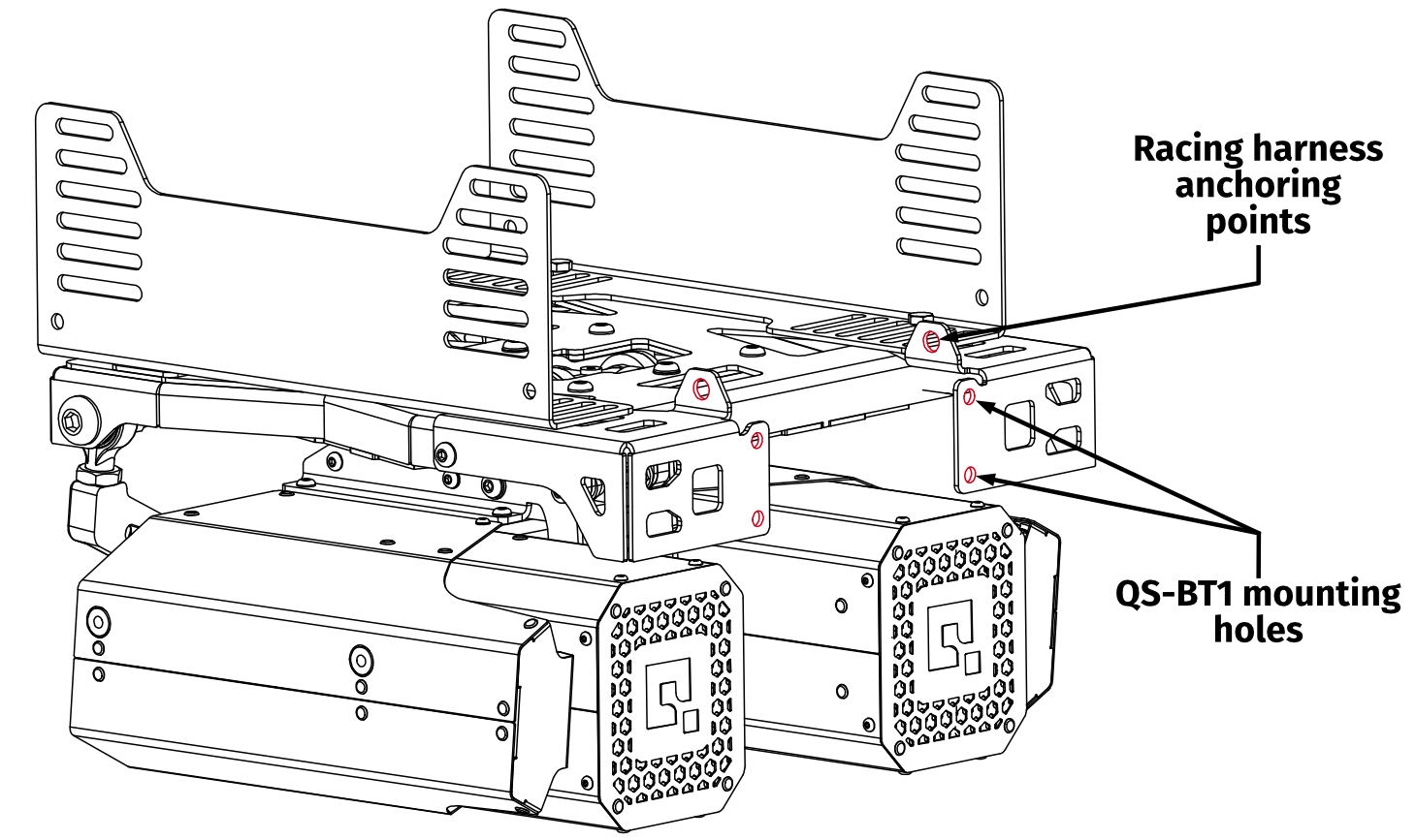
3.5 Racing harness installation
Revision B of the device features mounting holes for racing harness in the top frame. User can use eye-ring nuts (hardware not included) as per illustration below. Depending on the setup, it is also possible to bolt the harness straight to the frame.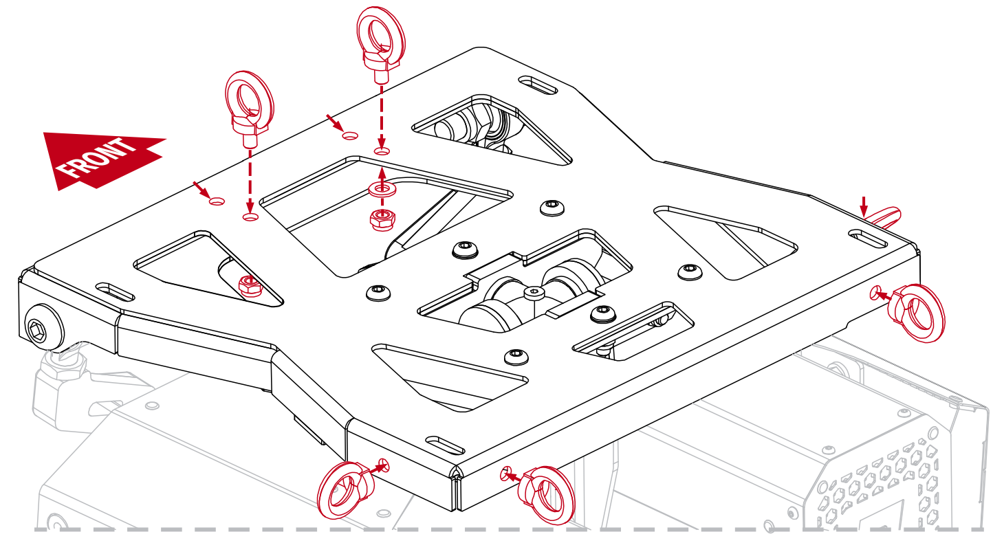
Warning
- All racing harness points MUST be mounted to a position that is moving along with the seat.
- QS-H13 is a dynamic seat mover with a long travel roll and pitch movement, creating moment of inertia on user's body - it is recommended to use a FIA certified racing seat and harness for safety.
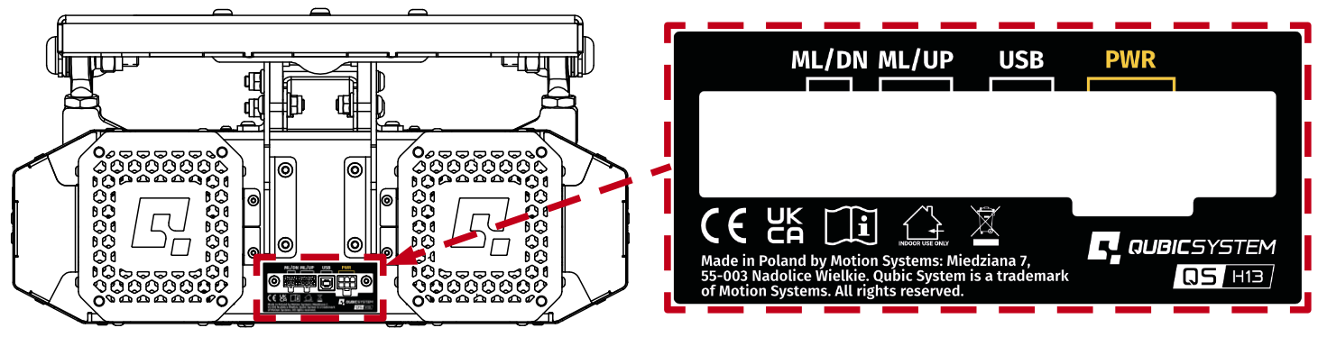
3.6 Cable connections
Info
Power cords used to power QS-H13 or other devices MUST NOT run alongside the QS-H13 's USB cable. They MUST be separated to allow for reliable connection with the PC.

Warning
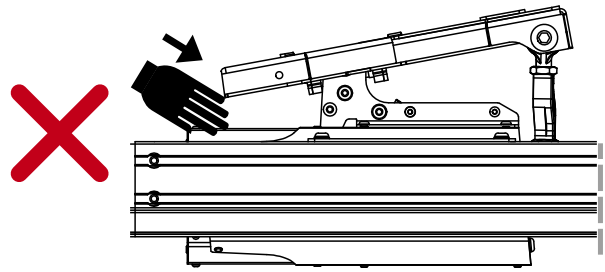
DO NOT reach under the top frame or attempt to connect/disconnect any cables while the device is powered ON. Doing so poses a serious risk of crushing injuries or severe limb damage due to unexpected movement of the frame or top frame installation.
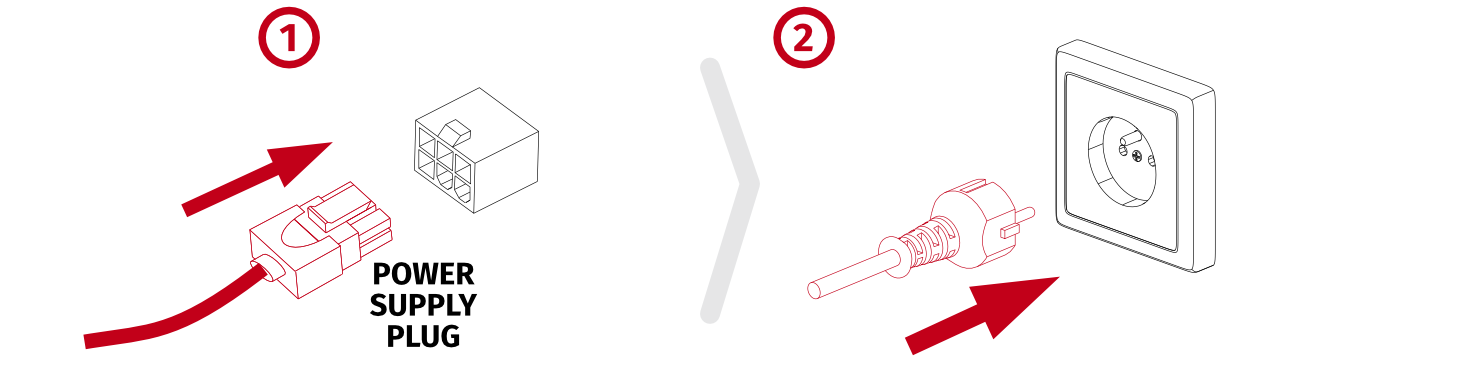
3.6.1 Before connecting power
Warning
The operation of connecting cables must ALWAYS be carried out with the power OFF.
3.6.2 Basic connection diagrams
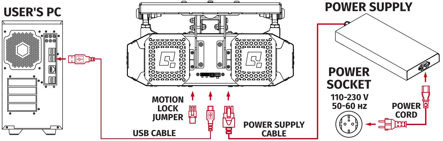
Info
If necessary, use only high-quality powered USB hubs. For reliable operation, use a short USB cable (less than 1 metre) and connect through a powered hub.
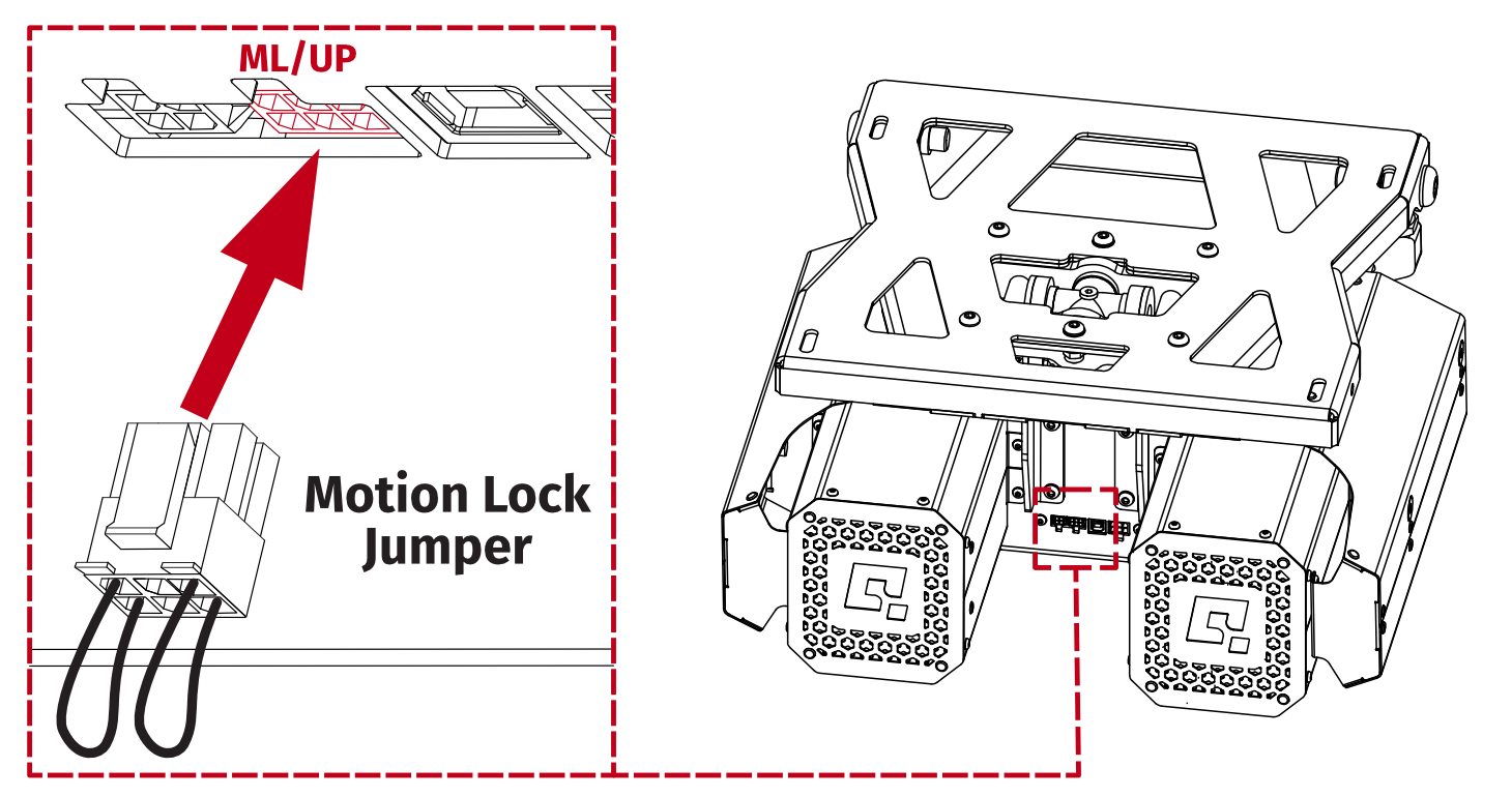
Warning
If QS-H13 is not included in Motion Lock circuit, Motion Lock jumper MUST be plugged in, as shown in the illustration below. More details on Motion Lock in section 3.7.
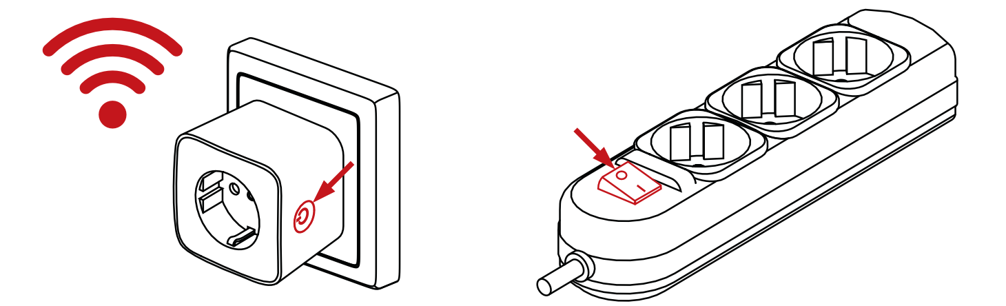
Info
To ensure safe power disconnection from QubicSystem device power supplies, it is recommended to use an external power switch — such as a power strip with a switch or a smart plug (rated for min. 10A).
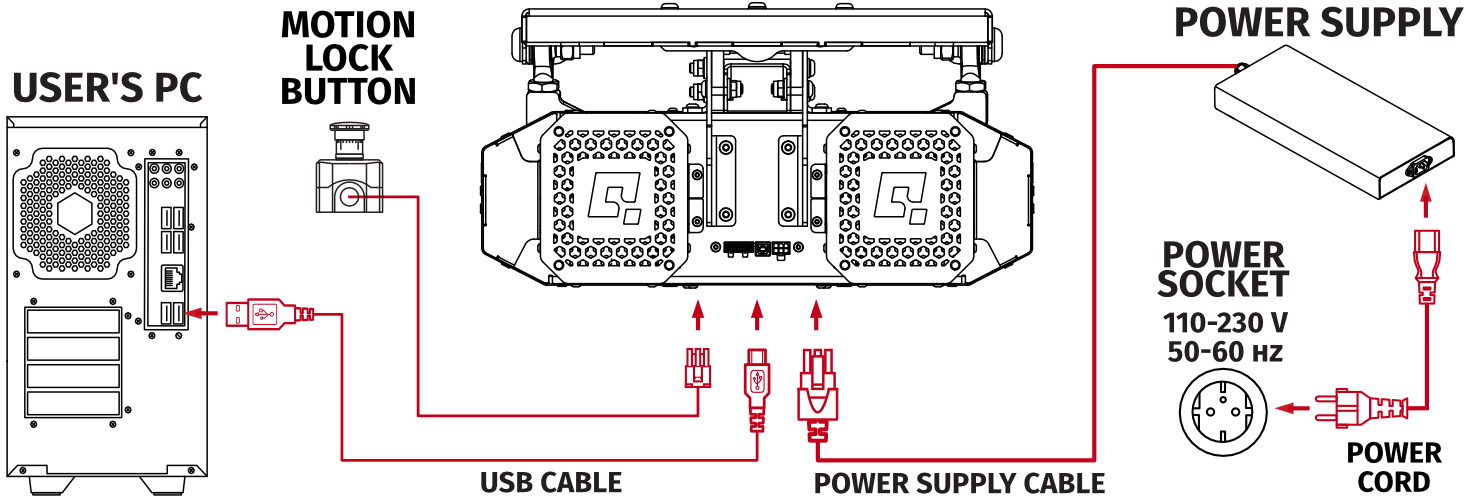
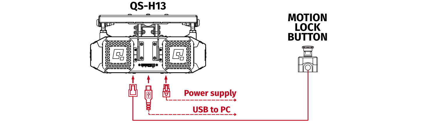
3.7 Implementing a Motion Lock button
The Motion Lock button, when pressed, provides an immediate emergency halt, overriding all active commands and stopping the platform instantly.It is not included but can be purchased separately from our distributors. To implement it into the system, disconnect the Motion Lock jumper and plug in the button.
- Motion Lock Switch should be mounted close to the operator or user of the machine - it has to be easily reachable in every situation.
- Check Motion Lock Switch AT LEAST once a month to reduce the possibility of unknown failure – more information available in chapter 4.
- Before getting on or off the machine ALWAYS activate Motion Lock (press the red button)
- In case of game crash or freeze, the Motion Lock Switch must be pressed before getting off the machine.
Info
Motion Lock input is not SIL/PL (safety integrity level/performance level) rated and DOES NOT guarantee safety. If you wish to achieve specific SIL/PL ranking, consider introducing a power cut-off device that is controlled by an external safety relay and cuts off the power to all interconnected devices.
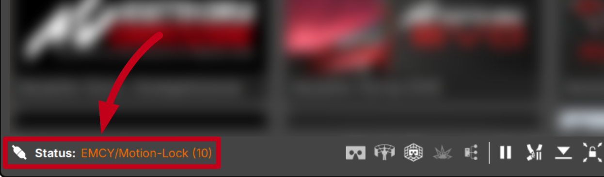
Info
To check if the QS-H13 is in the Motion Lock mode - go to QubicManager application main window. Platform status is displayed in the lower left corner of the main application window:
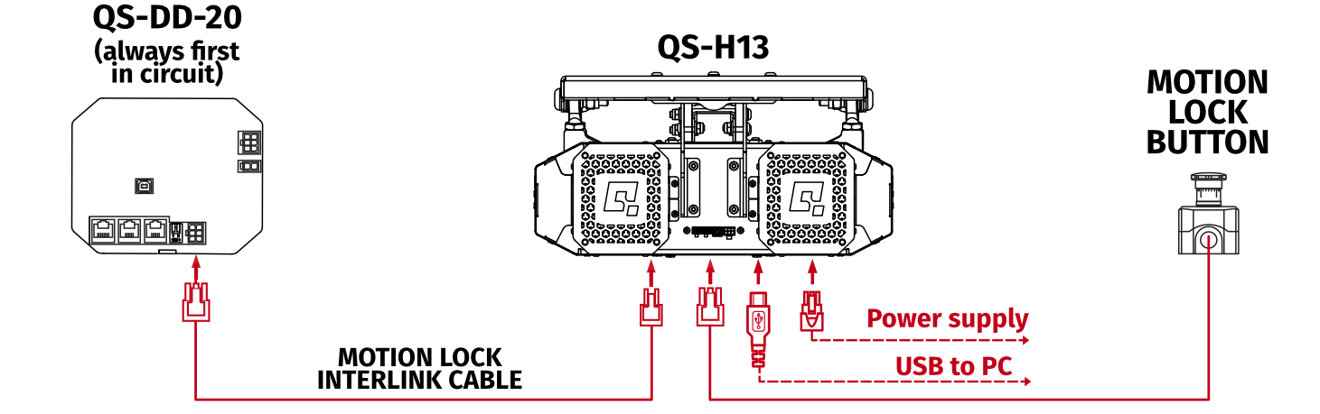
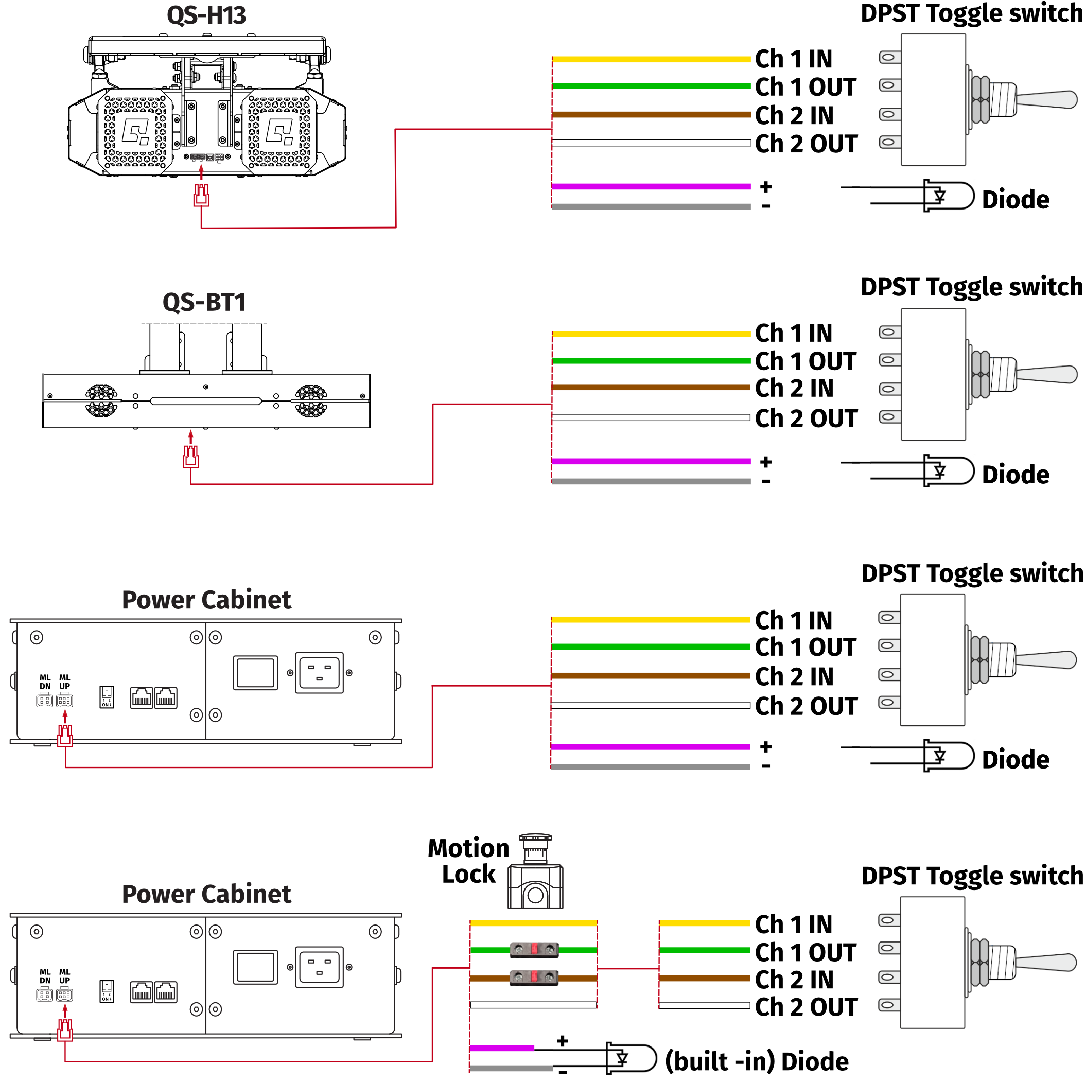
3.7.1 Motion Lock connection diagrams
It is recommended to include QS-H13 into a single Motion Lock circuit, if you are running other QS-series devices. Refer to diagrams below.Warning
- All Motion Lock connections must be performed with power OFF.
- Motion Lock interlink cables have different ML/UP (6 pin) and ML/DN (4 pin) plugs on each side.
- Motion Lock is not a standalone device - QS-H13 must be plugged in to power and via USB to PC.
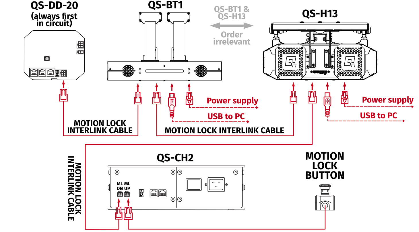
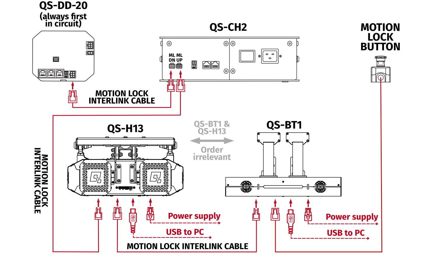
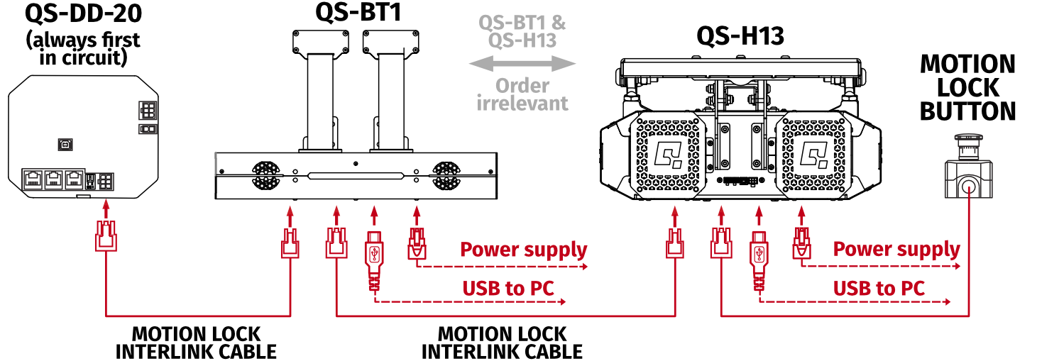
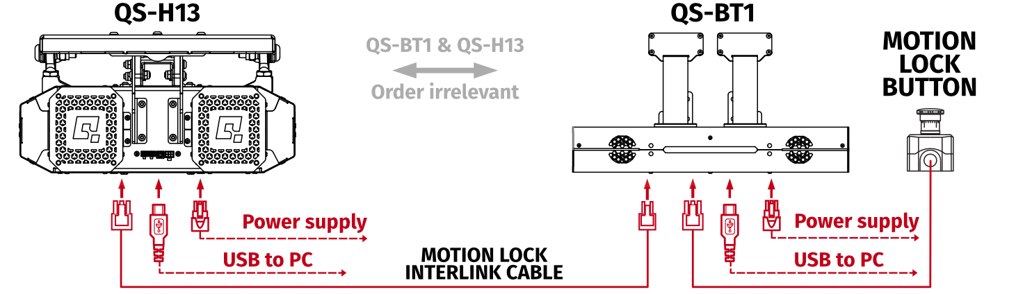
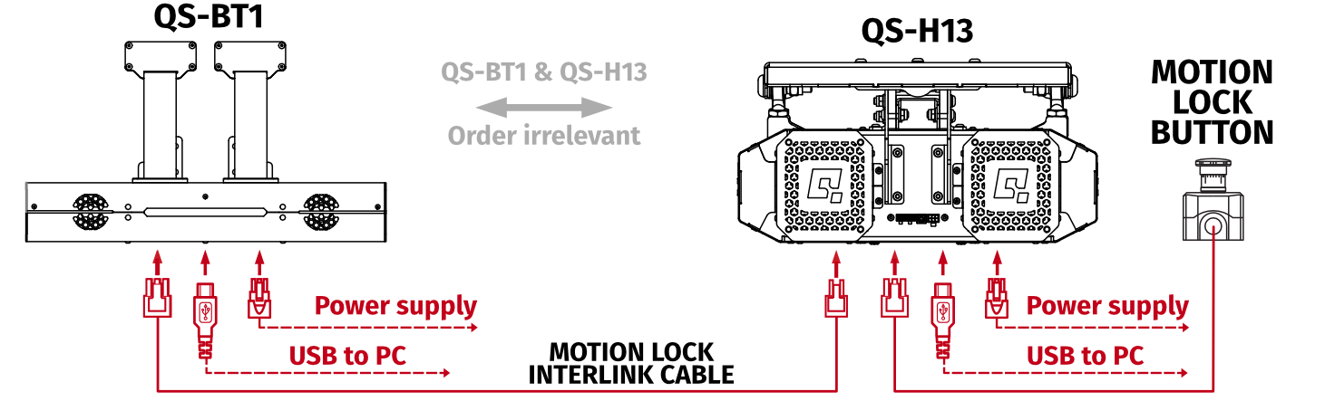
Info
QS-H13 and QS-BT1 in motion lock connection can be interlinked in any order.
3.7.2 Implementing non-factory Motion lock switch
For non-factory Motion Lock plug setup, you must assemble plug and connectors as shown below: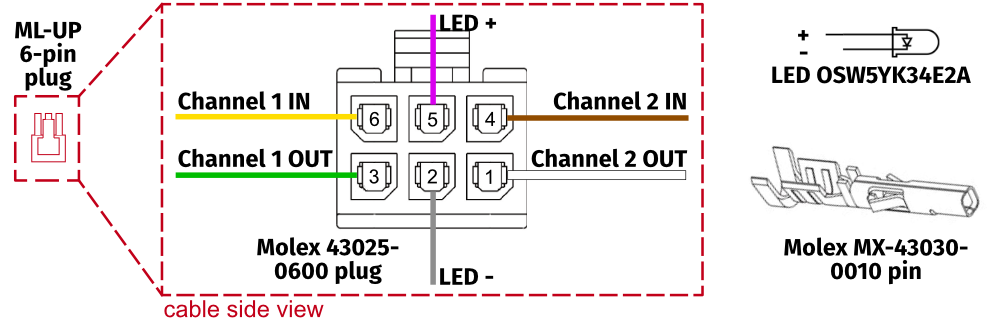
3.8 Post-assembly checklist
After successfully connecting the QS-H13 to the PC and installation to the platform - check if everything is ready to operate, before powering it ON: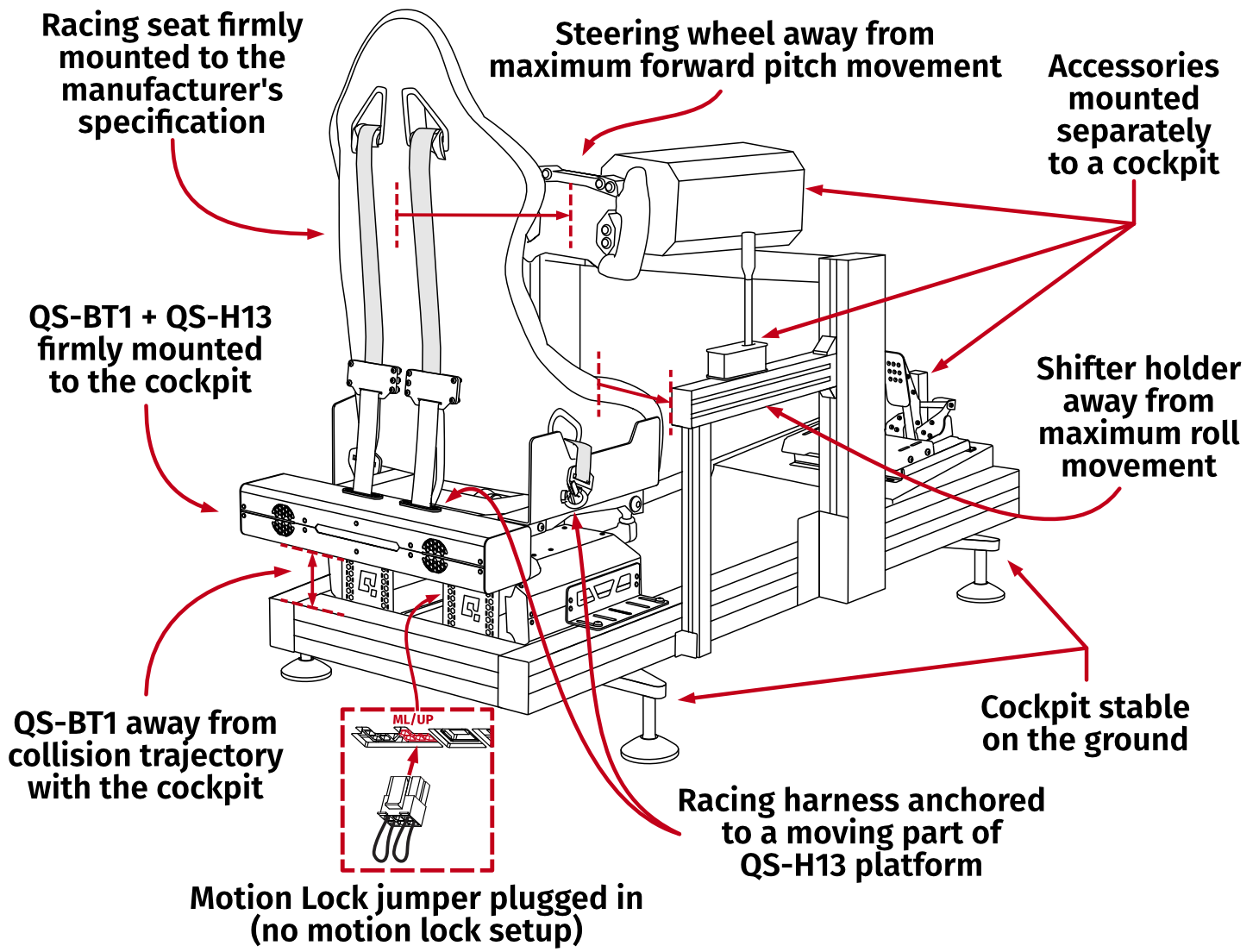
Info
For details and guidelines on correct QS-BT1 and racing harness assembly - see QS-BT1 user manual.
3.9 Software Installation
Info
Note down the QS-H13 serial number before installation as it is needed to access software download page.
To download the software visit: QubicSystem.com/Download
Once the QS-H13 is mounted and checked for clearance:
- Connect the device according to the interconnection diagram without connecting the power supply unit to the wall socket.
- Download Qubic Manager Software.
- Enter the serial number located on the identification label.
- Proceed with the installation steps and launch the application.
- Make sure the Motion Lock jumper is plugged in. If Motion Lock button is implemented - check its position and unpress, if needed.
- Connect QS-H13 Power Supply Unit's power cord to the wall socket.
- The QS-H13 will perform a start-up calibration.
Warning
- User may seat in the QS-H13 during the calibration run - be aware of the movement.
- DO NOT change the payload during the start-up calibration.
- If Qubic Manager has recognized the QS-H13 correctly, the status of the machine visible in the lower left corner will change to Parked/Centered.
 WarningIf the device did not connect correctly:
- Go over the cable connections - compare the connections to the diagram again, look for loose plugs or damaged cords.
- Go to Troubleshooting section.
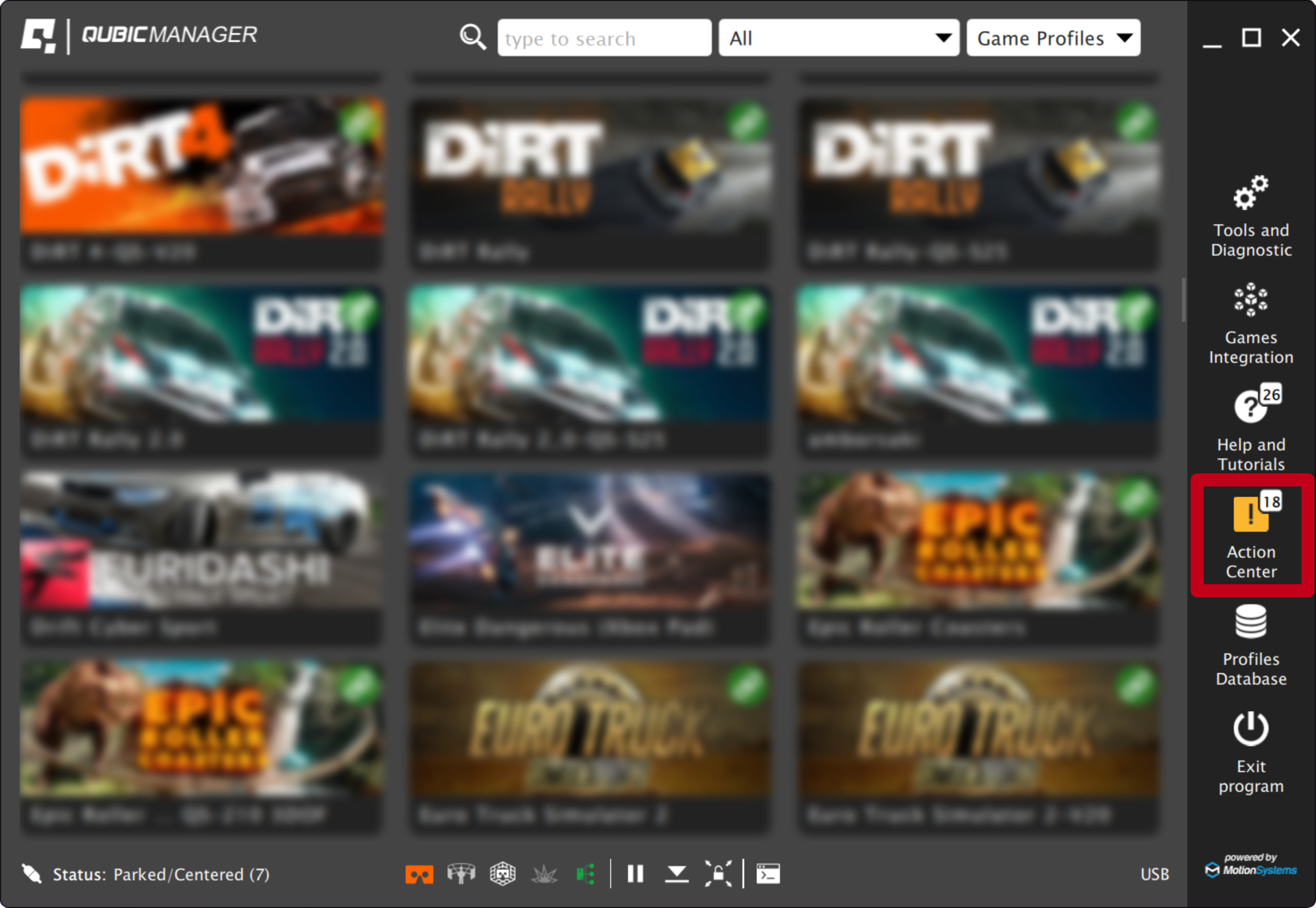
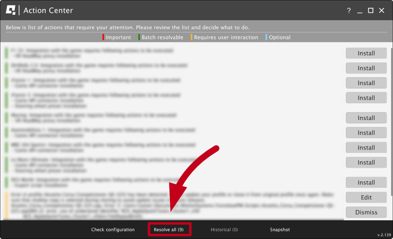
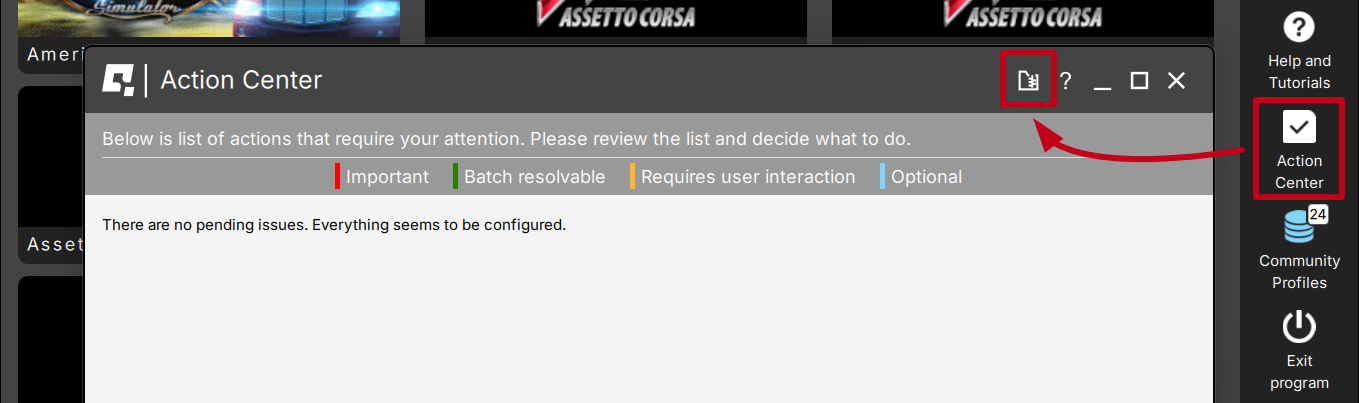
- Check Action Center on the right side panel for a list of actions that requires attention:
- It is possible to solve them one by one or by pressing the Resolve All button. Firmware update may require additional confirmation in the dialogue box.
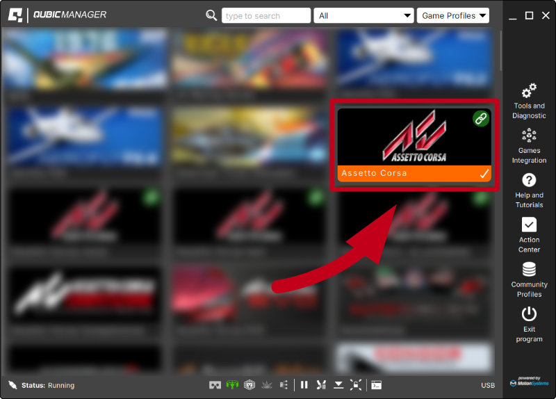
- Close the Action center window and return to the main application window. Choose the game and check profile details by clicking on the game tile.
InfoDefault profiles are integrated with the software and do not require additional installation. List of supported games is available at: QubicSystem.com/Supported-games.
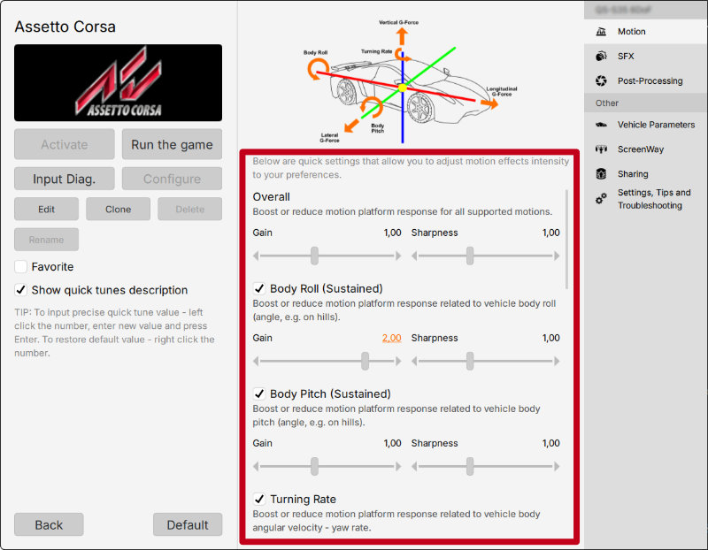
- Adjust the motion effects intensity up to your preferences in the game profile window. Scroll down to see all of the settings.
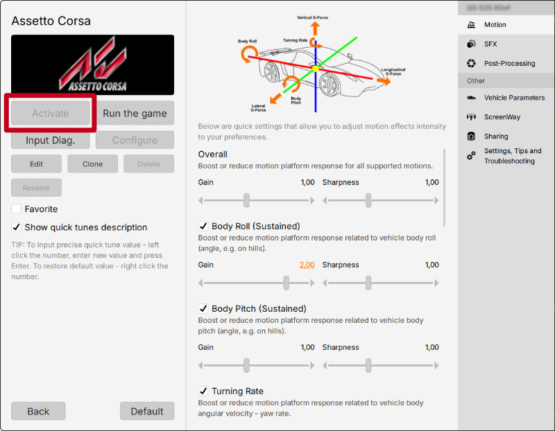
- Activate a profile by clicking the Activate button.
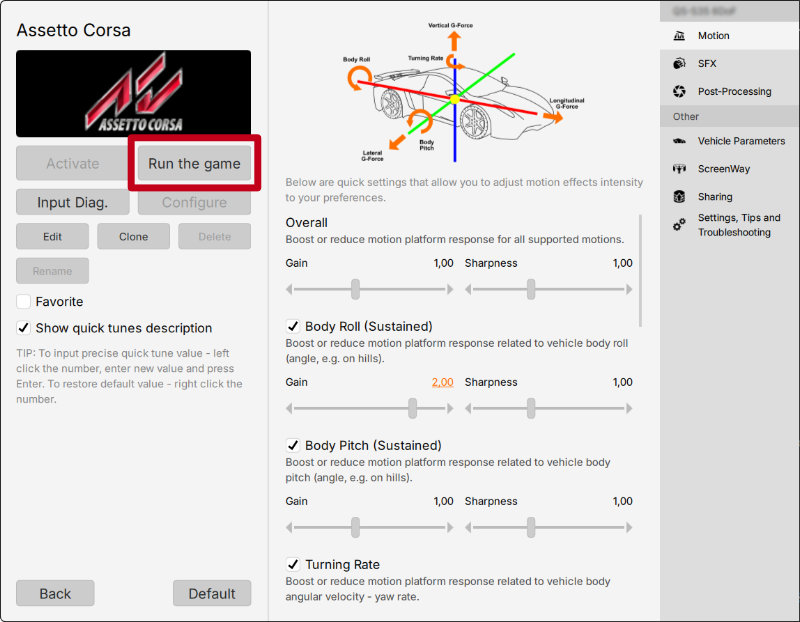
- Launch the game by clicking the Run the game button.
- You can also adjust the settings during the game simulation by pressing ALT+TAB and switching between the applications - once the profile is active changes will apply instantly.
Info
Warning
The software is provided "as is", without warranty of any kind, express or implied, including but not limited to the warranties of merchantability, fitness for a particular purpose, and non-infringement. In no event will the authors or copyright holders be liable for any claim, damage, or other liability, whether in an action of contract, tort or otherwise, arising from, out of, or in connection with the software or the use or other dealings in the software.
The software sends anonymous usage data to the Motion Systems company. The data is used to improve the software and game profiles. The data is not used for advertising purposes.
4 Maintenance and Cleaning
Info
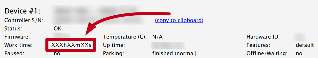
Cleaning should be conducted every 160 working hours or once a month.
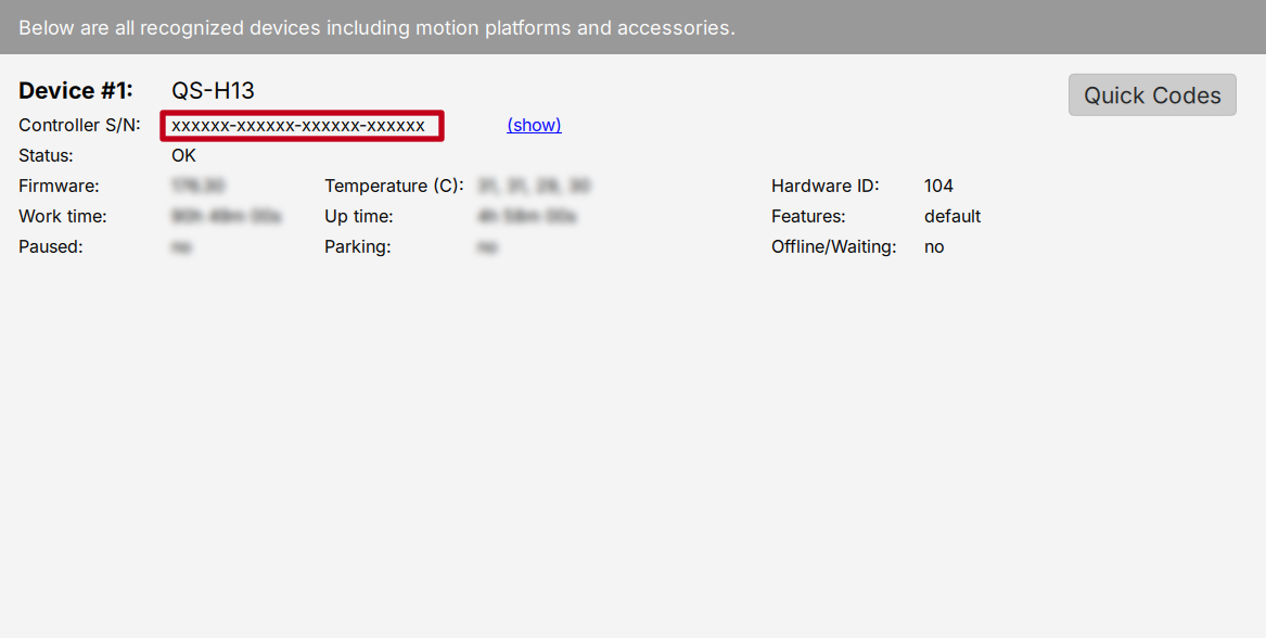
To see the working hours counter, go to Tools and diagnostics → Devices. It is displayed in the QS-H13 device listing:
4.1 Checking the Motion Lock button
Skip this section if you run a setup with no Motion Lock button. At least once a month check if Motion Lock button is working correctly:- Before anyone steps into the cockpit - turn on the QS-H13 .
- Push the red Motion Lock button.
- The machine should stop and not react to any signal.
- Turn on a simulation or a game to confirm that - with a correct profile activated proceed to a game or a simulation and engage movement.
✓
If the Motion Lock Button works correctly - platform does not react nor move in any way.
x
If the Motion Lock button does not work correctly - platform proceeds to simulate motion from the game/simulation. Check the cable connection and repeat the test. If the problem persists - contact technical support immediately.
4.2 QubicManager device statuses


Info
- ALL diagnostics and cable connection inspections MUST be performed with the device powered OFF.
- If any of error statuses persist after performing the troubleshooting steps - please contact technical support.
5 Troubleshooting
Warning
DO NOT attempt to do any repairs by yourself. It could be dangerous and will result in loss of warranty! Repairs should be consulted with technical support and then performed by a qualified technician.
- Check Action Center in QubicManager.
- Check all cable connections in the device.
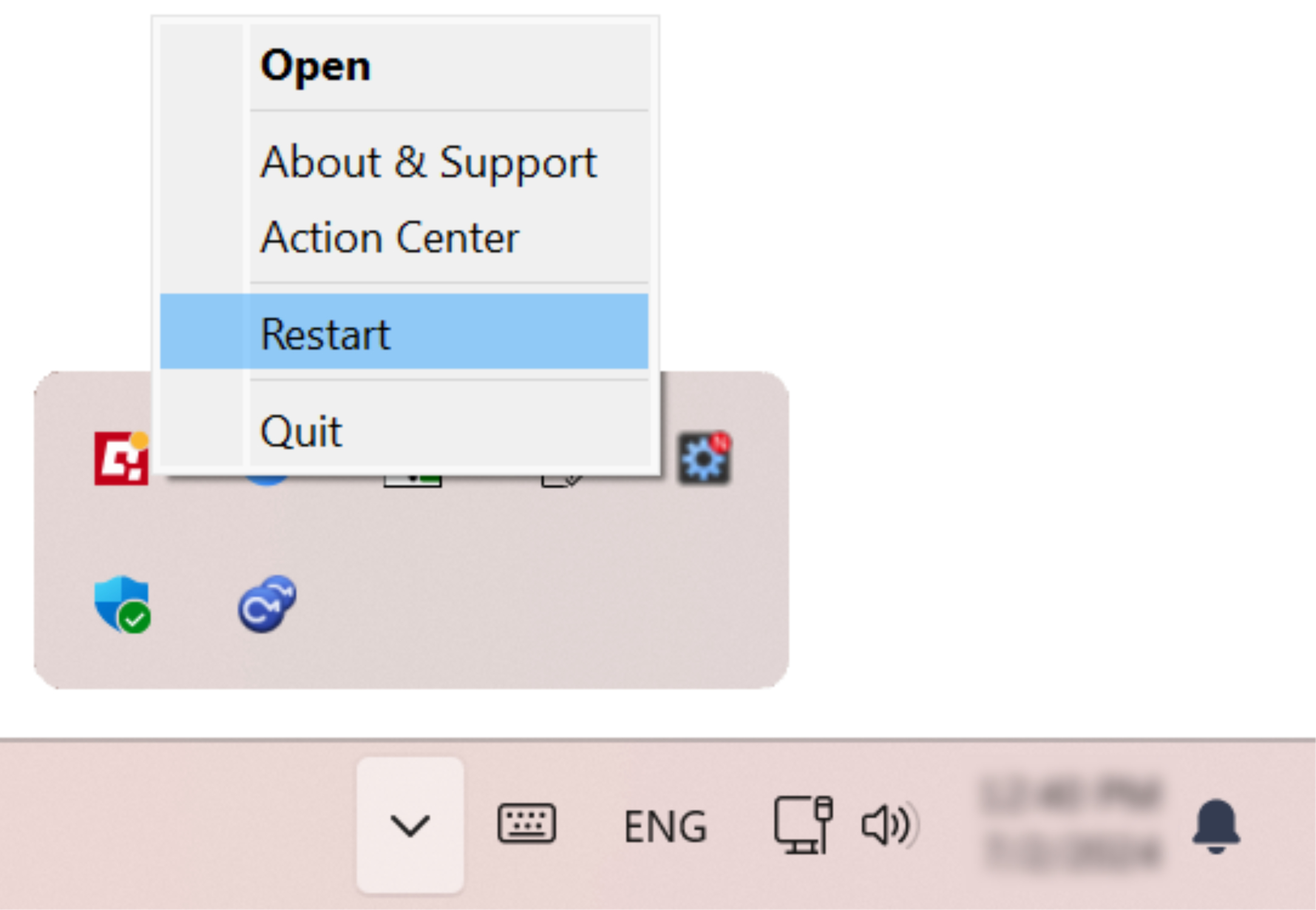
- Restart QubicManager application by right-click on the application icon in the system tray and selecting Restart:
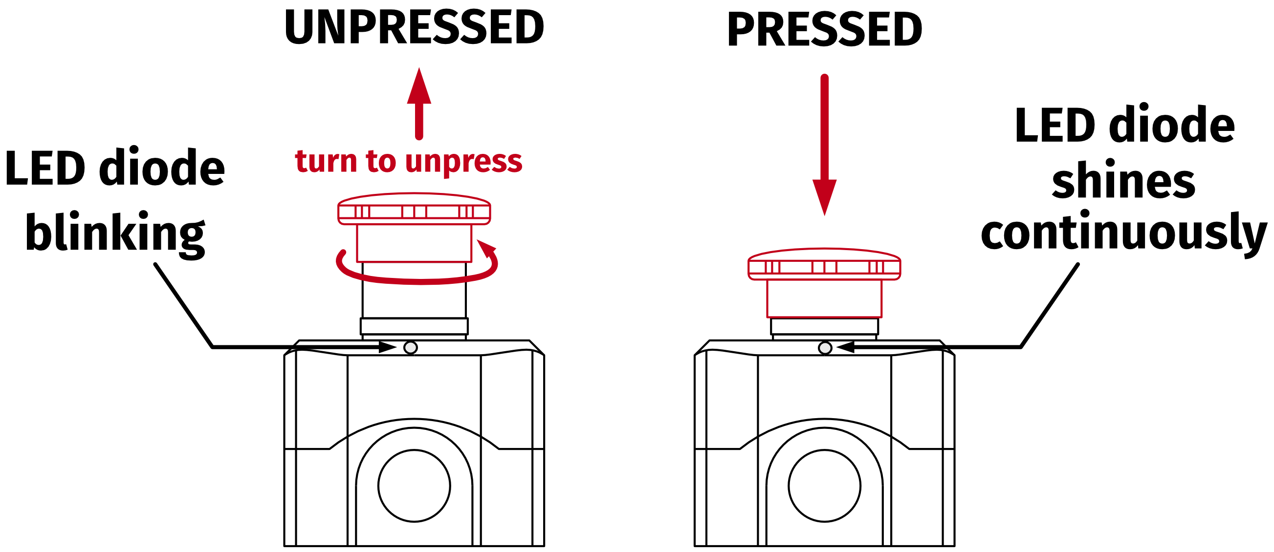
- If your device is equipped with a Motion Lock button - check its position (should be unpressed to activate the motion) :
- Try different USB ports (also try bypassing the USB hub by a direct PC connection).
- If a problem occurred abruptly, it could be caused by a thermal protection. Turn off the QS-H13 , disconnect it from power outlets and wait at least 15 minutes to let it cool down. Try turning it on again later.
- In case of any unclear electrical issues, strange behavior or abnormal work conditions, contact technical support.
5.1 Common problems with solutions
- Problem: QubicManager software crashes on launch with an OpenGL error.
Solution long-term #1: This issue is caused by graphics drivers. Try to downgrade to a previous version of graphics drivers or check for updates.
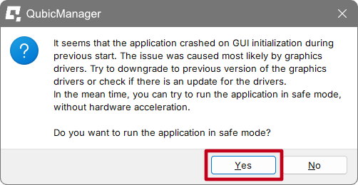
Solution short-term: To open the app, click OK on all the operating system errors. Restart the QubicManager software and you will be presented with a window:
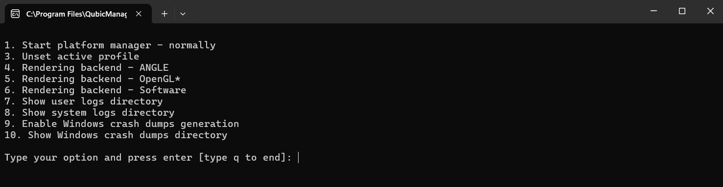
Click "YES" if you want run the application in Safe Mode (it will run a little slower). Solution long-term #2: In order to overwrite the OpenGL rendering backend permanently, type in troubleshooting in Windows search bar. Select Qubic System Troubleshooting Assistant.
 In the prompt window, type 6 on your keyboard and click Enter. Restart the QubicManager application.
- Problem: QS-H13 keeps disconnecting/does not connect at all.
Solution #1: Make sure QubicManager software is up to date. Go to QubicManager → "Tools and Diagnostic" (1) → "About / Support" (2) → check the software version (3)
 Compare it to newest software version listed on Qubic System website: QubicSystem.com/qschangelog → "Software" → "Changelog".
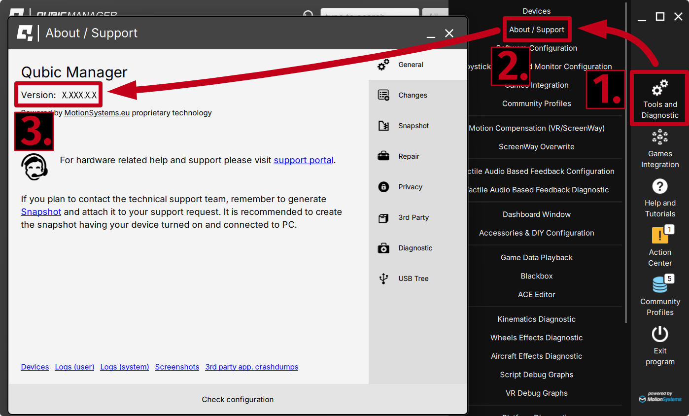 Solution #2: Check Action Center in QubicManager for pending issues. Click "Resolve all" button if there are any issues or resolve them one by one.
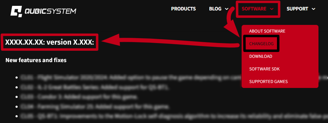 Solution #3: Pass over the USB Hub - connect the device directly to the PC. Solution #4: Plug the QS-H13 to a different USB Port. Solution #5: Replace the original USB cord (Type B USB plug).
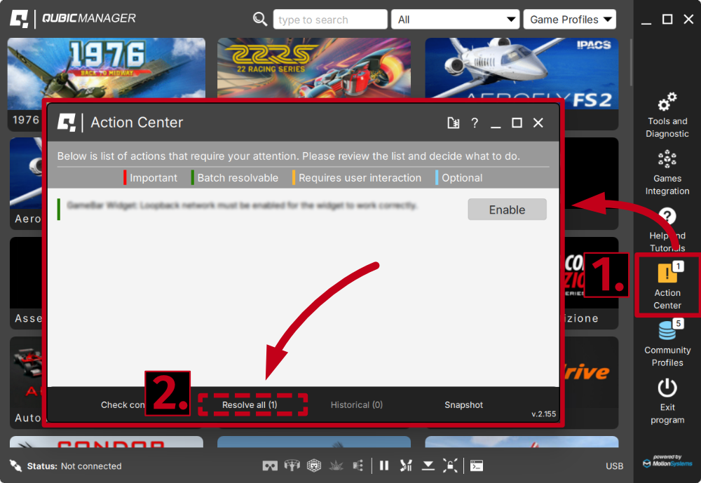 Solution #6: Separate power cords from QS-H13 's USB cable so that they do not run alongside each other.
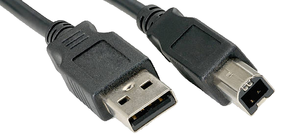 If none of the solutions above work - report the problem to Technical support via application form on the Motion Systems website and include a snapshot file (section 5.2).
5.2 Creating a snapshot
A snapshot is the easiest and fastest way to diagnose a problem. If you send in the zip file generated in the snapshot menu along with a description of the problem, technical support receives all the necessary information about the product and its configuration. It can be then analyzed to provide the best solution.Info
The QS-H13 and all interconnected Power Cabinets MUST BE be powered up when creating the snapshot.
- Open the main window of the QubicManager application.
- Go to Tools and Diagnostic → About / Support.
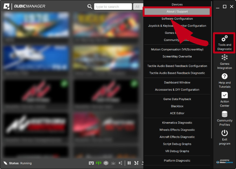
- Open the Snapshot window:
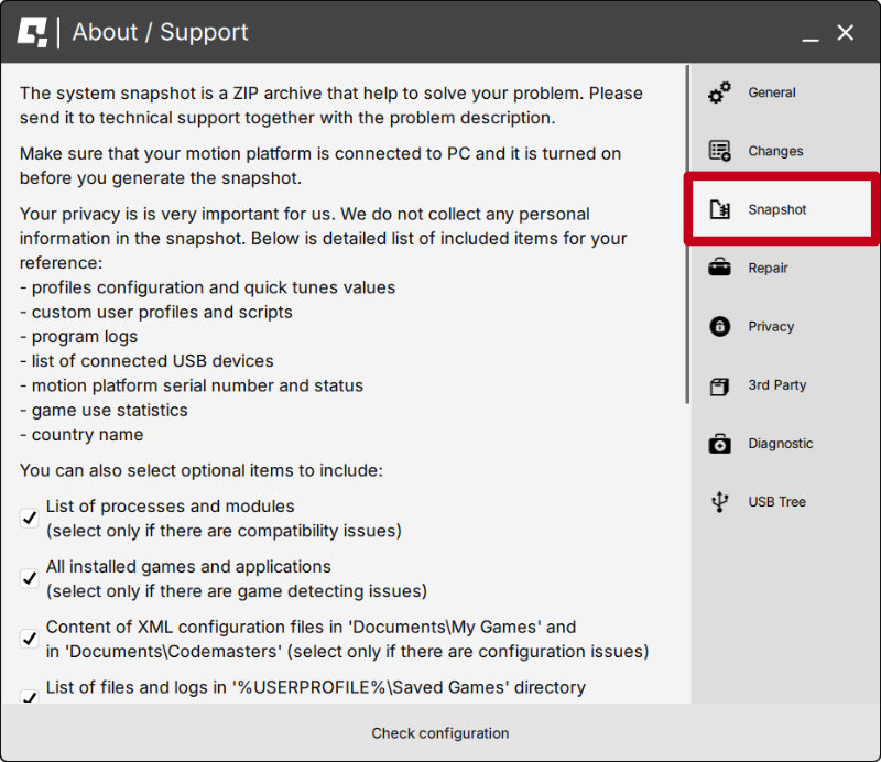
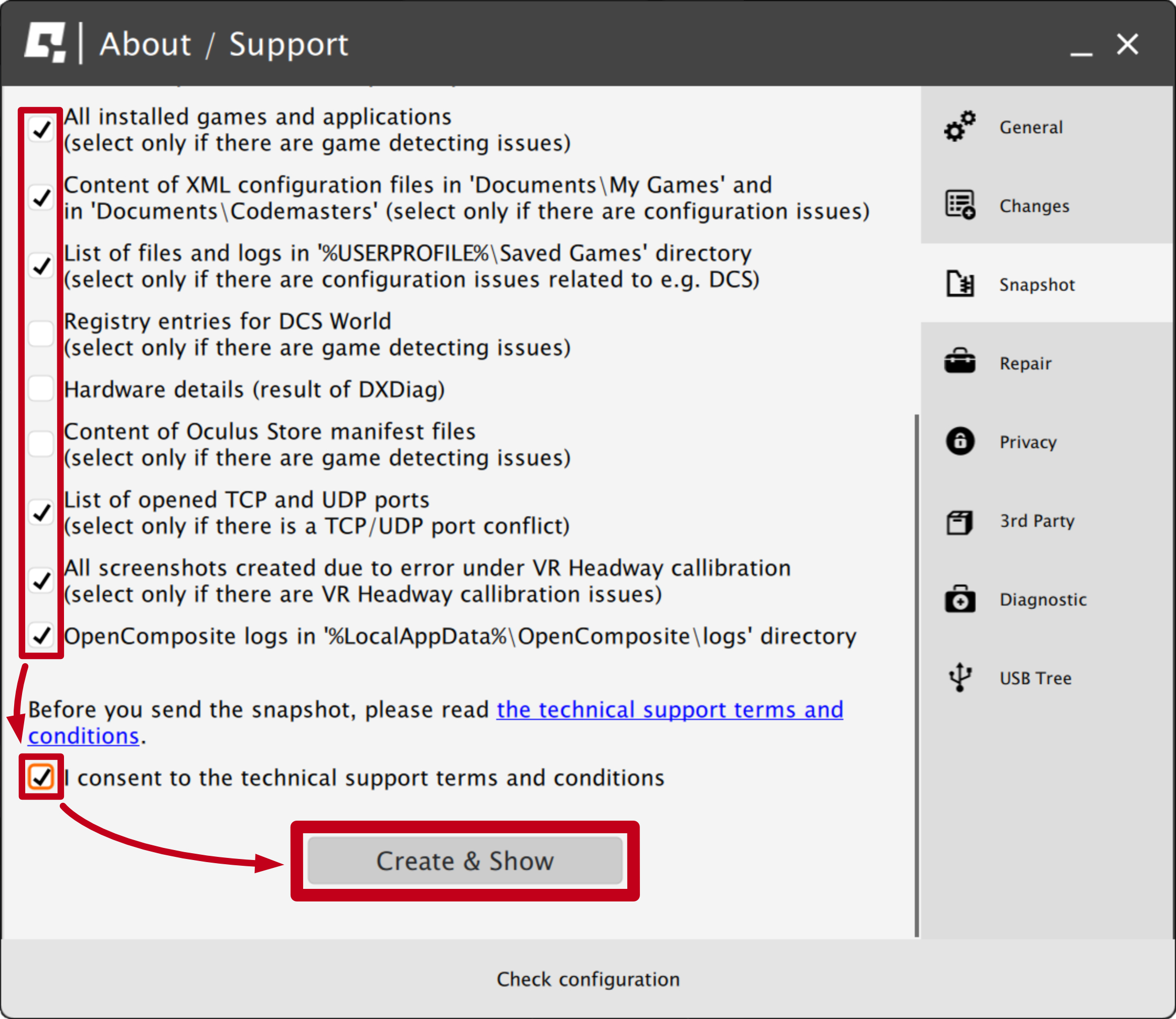
- Select data that will be included in the snapshot.
- Scroll down, consent to the technical support terms and conditions and select Create & Show:
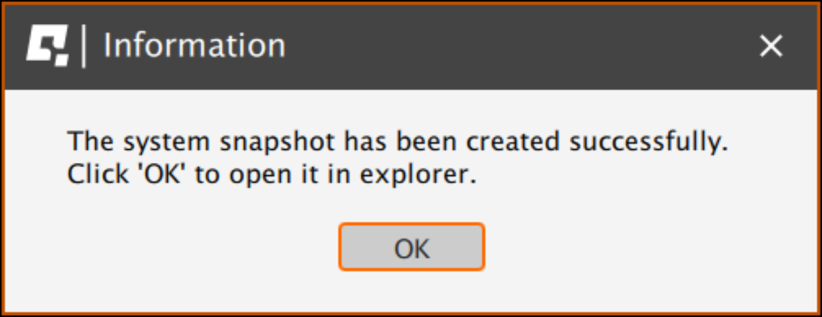
- The snapshot has been created, click the OK button - the folder with the snapshot ZIP file will open.
- Attach the snapshot ZIP file to your support request.
5.3 Discord channel
We strongly recommend joining our discord channel, where our growing community is sharing amazing tips and ideas of how to set up, use and tune the Qubic System products. You can also send questions for our staff or get answers directly from the community.
Join our discord channel by following the invitation link:

6 Conformity information

The QS-H13 meets the requirements of CE marking and relevant regulations of the EMC Directive 2014/30/EU.
7 Environmental Impact and Disposal

DO NOT dispose of this product with standard household waste but drop it off at a collection point for the disposal of Waste Electrical and Electronic Equipment for recycling.
- Metal parts should be scrapped.
- Electric and electronic components should be disposed of in the specialized disposal center.
- Other materials should be sorted and disposed of accordingly to the local law and regulations.
8 Liability Disclaimer
If permitted under applicable law, Motion Systems and its subsidiaries disclaim all liability for any damages caused by one or more of the following:- The product has been modified, opened, or altered.
- Failure to comply with assembly instructions.
- Inappropriate or abusive use, negligence, an accident (an impact - for example).
- Normal wear.
Info
If permitted under applicable law, Motion Systems and its subsidiaries disclaim all liability for any damages unrelated to the material or manufacturing defect with respect to the product (including, but not limited to, any damages caused directly or indirectly by any software, or by combining the QS-H13 with any unsuitable element or other elements not supplied or not approved by Motion Systems for this product).
9 Warranty
Motion Systems warrants to the consumer that this product shall be free from defects in materials and workmanship, for a warranty period which corresponds to the time limit to bring an action for concerning this product. For commercial customers there is a one (1) year limited warranty, starting on the original date of purchase. For non-commercial customers there are two (2) years warranty, starting on the original date of purchase. Within the warranty period, the product will be repaired or replaced free of charge, excluding shipping charges. This warranty shall not apply:- If the product has been modified, opened, altered, or has suffered damage as a result of inappropriate or abusive use, negligence, an accident, normal wear, or any other cause unrelated to a material or manufacturing defect (including, but not limited to, combining the QS-H13 with any unsuitable element, including in particular power supplies, chargers, or any other elements not supplied or approved by Motion Systems for this product).
- In the event of failure to comply with the instructions provided by technical support.
- To software (said software being subject to a specific warranty).
- To accessories (cables, cases, for example).
- If the product was sold at public auction or if the product has suffered damage as a result of force majeure: flood, fire, earthquake, storm.
10 Copyright
Qubic System is a trademark of Motion Systems. All rights reserved. All the contents in this user manual are the intellectual property of Motion Systems. No part of this manual, including the products and software described in it, shall be modified or translated into any language without the prior written permission of Motion Systems. Specifications and information in this manual are subject to change at any time without obligation to notify any person of such revision or changes. Illustrations are not binding.Info
Trademark Notice - All brand names, icons, and trademarks that appeared in this manual are the sole property of their respective holders.
11 Manufacturer information
Qubic System is a brand
that belongs to Motion Systems
HQ address:
Miedziana 7 Street
55-003 Nadolice Wielkie
Poland
that belongs to Motion Systems
HQ address:
Miedziana 7 Street
55-003 Nadolice Wielkie
Poland


Info
In support queries please contact your reseller.